A joining method for wind turbine blade shells

Active Publication Date: 2016-09-29
LM WP PATENT HLDG
View PDF7 Cites 10 Cited by
  • Summary
  • Abstract
  • Description
  • Claims
  • Application Information

AI Technical Summary

Benefits of technology

[0037]By providing the laminate from the same material as the blade shells, accordingly there is no difference in the stiffness properties between the blade shells and t

Problems solved by technology

The adhesives used in such bonding areas add considerable weight and cost to the final blade structure.
In addition, the use of such adhesives can result in the formation of structural cracks

Method used


Image

  • A joining method for wind turbine blade shells
  • A joining method for wind turbine blade shells
  • A joining method for wind turbine blade shells

Examples


Embodiment Construction

[0066]An embodiment of the invention will now be described, by way of example only, with reference to the accompanying drawings, in which:

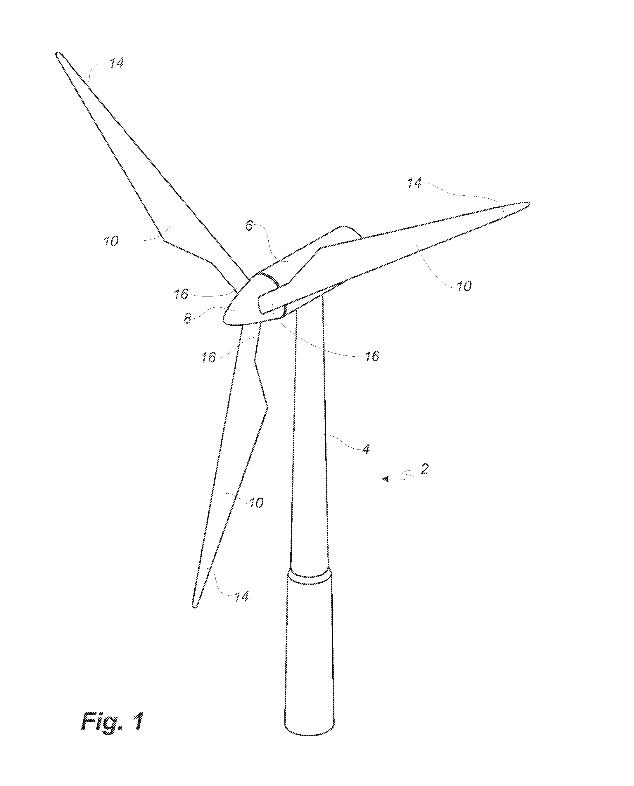
[0067]FIG. 1 shows a wind turbine;

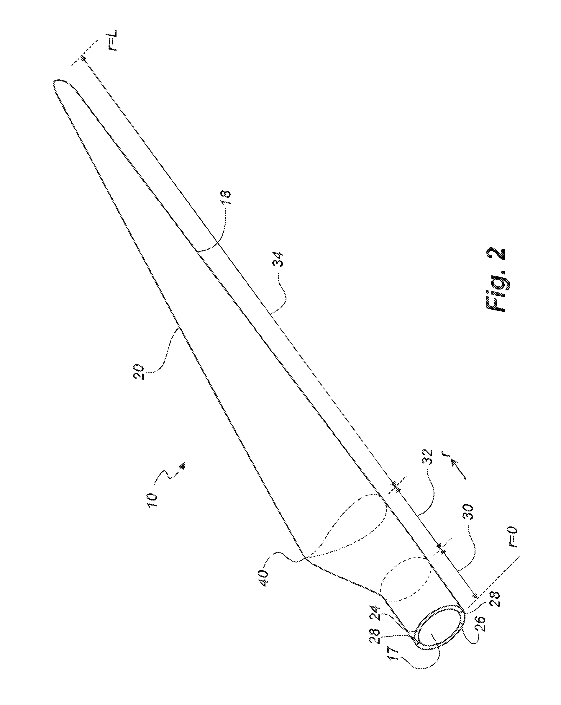
[0068]FIG. 2 shows a schematic view of a wind turbine blade according to the invention;

[0069]FIG. 3 shows a schematic view of an airfoil profile of the blade of FIG. 2;

[0070]FIG. 4 shows a schematic view of the wind turbine blade of FIG. 2, seen from above and from the side;

[0071]FIG. 5 illustrates an enlarged cross-sectional view of a leading edge adhesive bond for a prior art wind turbine blade; and

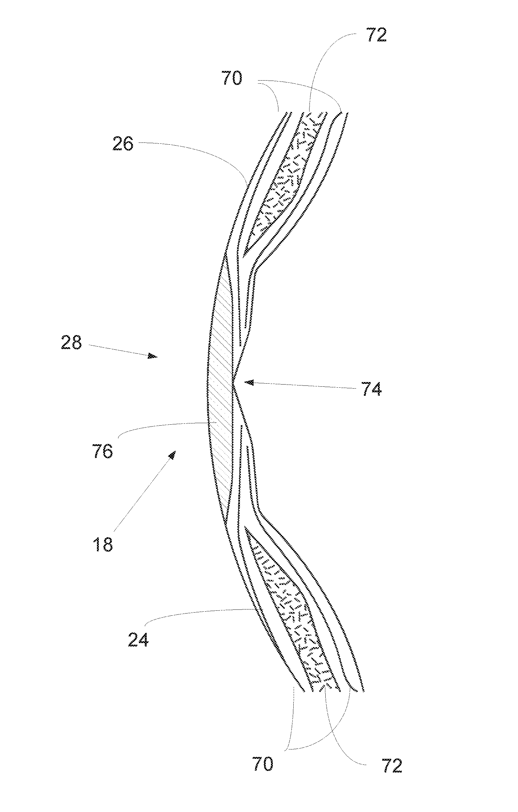
[0072]FIG. 6 illustrates an enlarged cross-sectional view of a bond for a wind turbine blade according to the invention, along a wind turbine blade leading edge.

[0073]It will be understood that elements common to the different embodiments of the invention have been provided with the same reference numerals in the drawings.

[0074]FIG. 1 illustrates a conventional modern upwind wind turbine 2 according to the so-called “...


PUM

PropertyMeasurementUnit
Areaaaaaaaaaaa
Stiffnessaaaaaaaaaa

Abstract

A method of manufacturing a wind turbine blade is described, the blade being formed from at least a pair of blade shells being joined together. For at least a portion of the wind turbine blade, the blade shells are joined by an overlamination applied between the edges of the blade shells, thereby substantially reducing or eliminating the need for a structural adhesive to join the blade shells, particularly in the area of the leading edge of the blade or the root region of the blade trailing edge. The overlamination can be formed from the same material as the blade shells themselves, thereby minimising the possibility of structural faults or cracks due to differences in materials or stiffness levels at the interface between the blade shells.

Description

FIELD OF THE INVENTION[0001]The present invention relates to a system and method for joining sections of wind turbine blades, in particular for joining wind turbine blade shells to form a wind turbine blade.BACKGROUND OF THE INVENTION[0002]Wind turbine blades are generally made from composite materials, in particular glass and / or carbon fibre material which is infused with a resin and cured to form a solid structure.[0003]A known approach to wind turbine blade manufacturing is to form separate blade shell sections. Such shells are formed by the arrangement of layers of fibre material in suitably-shaped moulds which are infused with a resin which is subsequently cured. The solid blade shells can then be adhered together to form a larger wind turbine blade structure. Such shells are traditionally formed as half-portions of a wind turbine blade, e.g. a first shell corresponding to an upwind- or pressure-side of a wind turbine blade and a second shell corresponding to a downwind- or suc...

Claims


Application Information

Patent Timeline
IPC IPC(8): B29C65/00F03D1/06F03D1/00B29C65/50
CPCB29C66/54B29C65/5014B29C65/505B29C66/12261B29C66/721F05B2280/6003F03D1/0675F03D1/001B29C70/30B29L2031/085B29C66/723B29C65/483B29C65/5021B29C65/52B29C66/1226B29C66/221B29C66/223B29C66/7212B29C66/72329B29C66/727B29D99/0028B29C66/71F03D13/10B29C65/5042B29C66/02241B29C66/02245Y02E10/72Y02P70/50B29C70/304B29K2307/04B29K2309/08B29K2031/00B29K2063/00B29K2067/00B29K2075/00
Inventor GARM, JESPER HASSELBALCH
Owner LM WP PATENT HLDG
Why Eureka
Try Eureka