Eureka AIR delivers breakthrough ideas for toughest innovation challenges, trusted by R&D personnel around the world.

Method for manufacturing deposition mask and deposition mask

a manufacturing method and mask technology, applied in the field of manufacturing deposition masks and deposition masks, can solve the problems of unfavorable uniform layer thickness distribution, inability to easily control the inclination angle of side walls of opening patterns, etc., and achieve the effect of easy control of the inclination angle and easy manufactur

Active Publication Date: 2016-09-29
V TECH CO LTD
View PDF2 Cites 15 Cited by
  • Summary
  • Abstract
  • Description
  • Claims
  • Application Information

AI Technical Summary

Benefits of technology

The present invention provides a method for manufacturing a deposition mask by using laser light to create an opening pattern. This method allows for easy control of the inclination angle of the mask's opening pattern, which allows for the creation of a thin deposition layer with uniform layer thickness. This method also reduces the likelihood of shadowing a substrate during deposition.

Problems solved by technology

Thus, the inclination angle of side walls of the opening pattern cannot be easily controlled.
Accordingly, when deposition is carried out with a deposition mask manufactured by the conventional method while scanning a substrate in one direction, the resultant thin layer shows non-uniform distribution of layer thickness in the direction crossing the scanning direction because the edge of the opening pattern in this direction shadows the substrate.

Method used


Image

  • Method for manufacturing deposition mask and deposition mask
  • Method for manufacturing deposition mask and deposition mask
  • Method for manufacturing deposition mask and deposition mask

Examples


Embodiment Construction

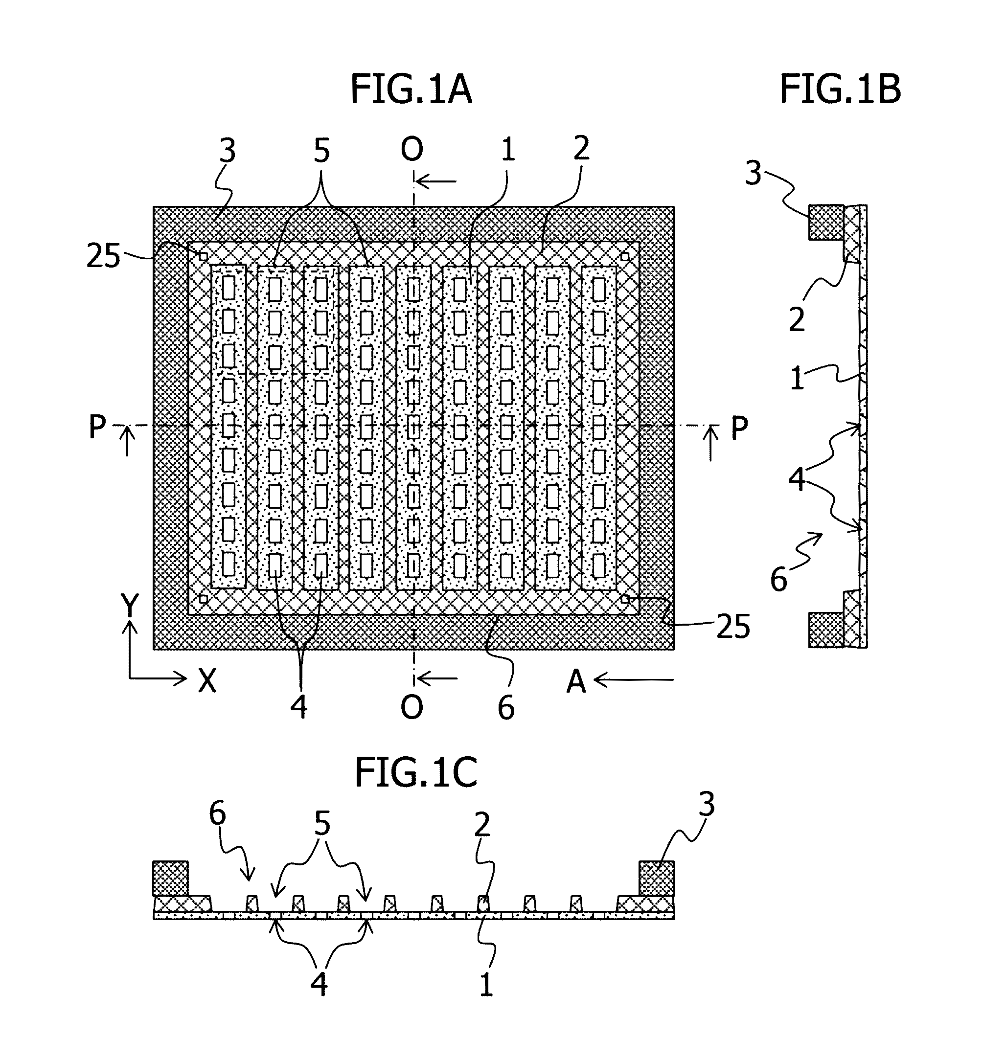
[0020]Hereinafter, embodiments of the present invention will be described in detail with reference to the accompanying drawings. FIGS. 1A to 1C show a deposition mask according to an embodiment of the present invention, in which FIG. 1A is a plan view thereof, FIG. 1B is a sectional view taken along line O-O of FIG. 1A, and FIG. 1C is a sectional view taken along line P-P of FIG. 1A. The deposition mask serves to form a deposition layer on a substrate through an opening pattern. The mask includes a film mask 1, a metal mask 2, and a metal frame 3.

[0021]The film mask 1 is used in close contact with the deposition substrate. The mask functions as a main mask for forming a thin layer pattern on the deposition substrate. A film applicable to the mask is, for example, a resin film made of polyimide, polyethylene terephthalate (PET), or the like with the thickness of about 10 μm to 30 μm. The film has plural opening patterns 4 of a polygonal shape (rectangle in this embodiment) in a plan ...


PUM

PropertyMeasurementUnit
thicknessaaaaaaaaaa
thicknessaaaaaaaaaa
thicknessaaaaaaaaaa

Abstract

The present invention provides a method for manufacturing a deposition mask, which irradiates laser light L to a resin film 20 to form an opening pattern 4 having a polygonal shape in a plan view, the method including a step of irradiating the laser light L that is shaped using a beam-shaping mask 10 having a light transmissive window 18 that allows the laser light L to pass therethrough with light transmittance gradually reducing with distance from an edge of the light transmissive window 18 on at least one of opposing sides thereof within an area outside the light transmissive window 18 to thereby form the opening pattern 4 having at least one pair of opposing side walls 4a that are inclined to open wide toward a surface of the film 20 to be irradiated with the laser light L, from a surface opposite to the irradiated surface.

Description

CROSS-REFERENCE TO RELATED APPLICATION[0001]This application is a continuation application of PCT / JP2014 / 082121, filed on Dec. 4, 2014.BACKGROUND OF THE INVENTION[0002]1. Field of the Invention[0003]The present invention relates to a method for manufacturing a deposition mask by irradiating a resin film with laser light to form an opening pattern, more particularly to a method for manufacturing a deposition mask so as to control the inclination angle of side walls of the opening pattern, and to a deposition mask manufactured by such method.[0004]2. Description of Related Art[0005]Conventional deposition masks include a mask layer having the thickness of 1 μm to 50 μm. The mask layer has at least one opening pattern corresponding to a deposition pattern. On the mask layer, a magnetic member is disposed not to cover the opening pattern of the mask layer (see JP 2009-249706 A, for example). The opening pattern of the mask layer is desirably tapered to open wide toward the surface facin...

Claims


Application Information

Patent Timeline
Patent Type & Authority Applications(United States)
IPC IPC(8): C23C14/04B23K26/073B23K26/066
CPCC23C14/042B23K26/066C23C14/50C23C14/24B23K26/073H01L21/027C23C16/042
Inventor MIZUMURA, MICHINOBU
Owner V TECH CO LTD
Why Eureka
Eureka Blog
Learn More