Blower and outdoor unit of air conditioner comprising same

a technology of air conditioner and outdoor unit, which is applied in the field of outdoor unit of air conditioner and blower, can solve the problems of increased power consumption, noise generation, and inability to uniformly introduce air current, so as to reduce the need for strength, reduce the weight, and reduce the effect of material cos

Active Publication Date: 2016-09-29
SAMSUNG ELECTRONICS CO LTD
View PDF14 Cites 23 Cited by
  • Summary
  • Abstract
  • Description
  • Claims
  • Application Information

AI Technical Summary

Benefits of technology

[0032]To decrease a weight applied to the noise prevention blade and decrease necessary strength so that a thickness of the noise prevention blade is maintained and material cost is decreased, it is preferable that the stator part include the hub in a substantially hollow cylindrical shape in which the inner circumferential end of the noise prevention blade is connected to the outer circumferential surface and the hub include a reinforcement rib structure in a radial shape.
[0033]For example, to prevent breaking a rotational balance of the propeller fan due to snow being accumulated on a central portion of the propeller fan in the bell mouth part and being in contact with the inner circumferential surface of the bell mouth part to be destroyed, it is preferable that a cover member which is installed to cover the downstream side of the hub and has a cone-shaped surface or dome-shaped curved surface be further provided. Accordingly, since the cover member has the curved surface, snow is not accumulated on the hub, and the noise prevention blades of the stator part may also be prevented from being damaged due to

Problems solved by technology

However, an air current may not be uniformly introduced into inlet ports installed at an upstream side of the bell mouth part based on an apparatus in which the blower is installed, therefore a suction flow rate may be distributed according to region.
Because of this, blowing efficiency may not be improved more than a certain level, and there is also a problem in that when the number of revolutions of a propeller fan is increased for increasing the suction

Method used


Image

  • Blower and outdoor unit of air conditioner comprising same
  • Blower and outdoor unit of air conditioner comprising same
  • Blower and outdoor unit of air conditioner comprising same

Examples


first embodiment

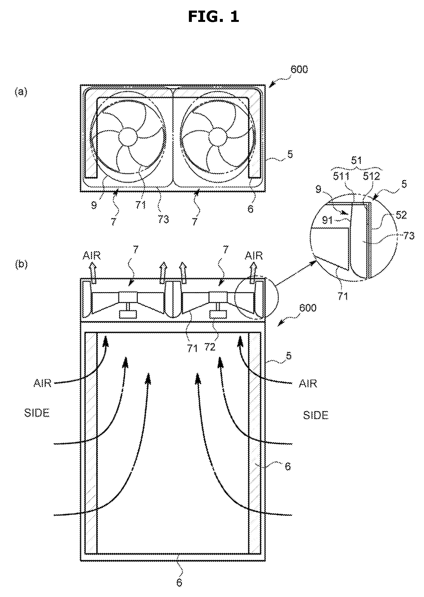
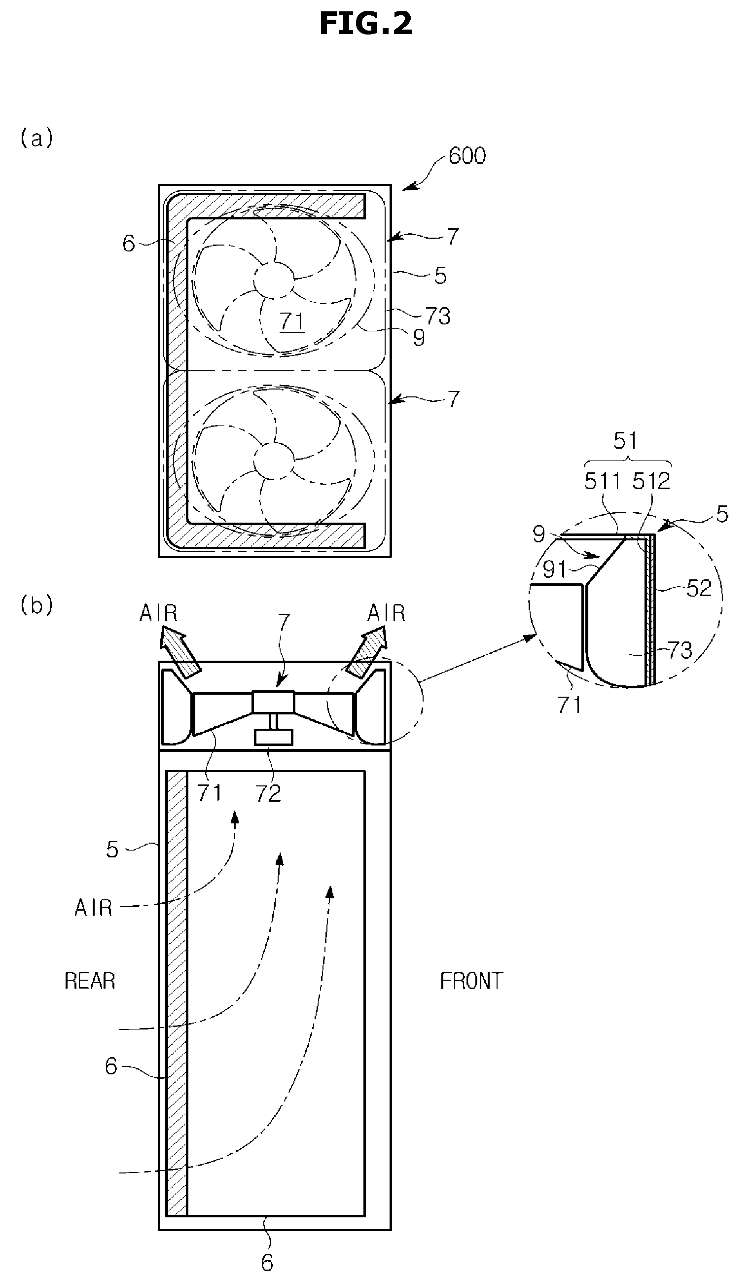
[0052]A blower 7 according to the present embodiment is a type of axial fan used for an outdoor unit 600 (hereinafter, simply referred to as the outdoor unit 600) for an air conditioner.

[0053]As illustrated in FIGS. 1 and 2, the outdoor unit 600 includes a casing 5 which is formed with a bottom plate (not shown) and side perimeter plates 52 and 51 in a substantially rectangular parallelepiped shape extending vertically, a plurality of heat exchangers 6 disposed at side and rear surfaces of the casing 5, and a plurality of (here, two) blowers 100 disposed adjacent to a top surface of the casing 5. In addition, the outdoor unit 600 has, so called, a vertical upright type in which air is introduced from a side surface of the casing 5 into an inside thereof by a vortex generated by the blower 100, comes into contact with the heat exchanger 6, and is discharged upward. In addition, the casing 5 accommodates various electric units (not shown) besides the heat exchanger 6.

[0054]Hereinafter...

second embodiment

[0085]Next, a second embodiment of the present disclosure will be described.

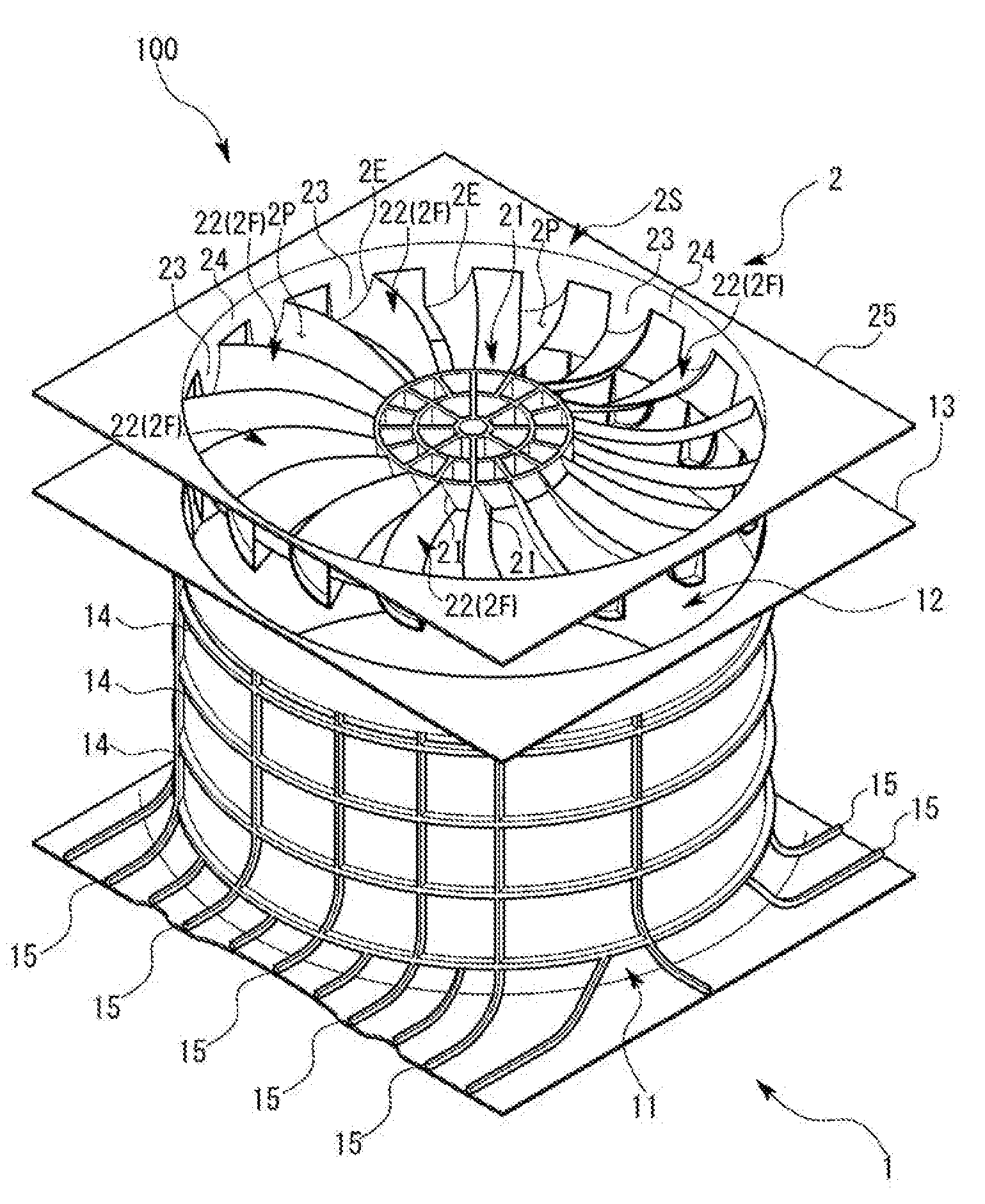
[0086]A blower 100 according to the present embodiment is formed by a resin injection mold, as illustrated in FIGS. 6 and 9, and includes a container-shaped molded object 1 formed in a substantially cylindrical shape and a molded blade part 2 in which a stator part 2F provided with a plurality of noise prevention blades 22 having a substantially flat rectangular parallelepiped shape is formed at a central circular portion. As illustrated in FIG. 6, the molded blade part 2 is assembled in the container-shaped molded object 1, and then the stator part 2F may be disposed at a predetermined position in the container-shaped molded object 1. In addition, a fan guide FG is installed at a downstream side of the molded blade part 2 to cover the stator part 2F.

[0087]As illustrated in FIGS. 6 and 9, the container-shaped molded object 1 is integrally formed with a bell mouth part 11 which is disposed to be spaced a pred...


PUM


Abstract

Provided are a blower, capable of suppressing noise occurring in a stator while significantly improving blowing efficiency, and an outdoor unit using the same. The present invention comprises: a bell mouth part spaced apart at a predetermined distance in the radial direction with respect to an outer circumferential end of a propeller fan; and a diffuser part installed on the downstream side of the bell mouth part, and having a flow path area which is enlarged from the upstream side toward the downstream side with a larger magnification rate than the magnification rate of the flow path area in the downstream end of the bell mouth part; and a stator part having a plurality of stators, wherein the stator part is arranged within the diffuser part.

Description

CROSS-REFERENCE TO RELATED APPLICATIONS[0001]This application is a continuation of PCT international application PCT / KR2014 / 011715 filed on Dec. 2, 2014 and claims the benefit of Japanese Patent Application Nos. JP2013-249308, filed on Dec. 2, 2013, and JP2014-157177, filed on Jul. 31, 2014, and Korean Patent Application No. 10-2014-0170184, filed on Dec. 2, 2014, in the Japan Patent Office and the Korean Intellectual Property Office, respectively, the content of each of the foregoing is incorporated herein by reference.BACKGROUND[0002]1. Technical Field[0003]The present invention relates to an outdoor unit of an air conditioner and a blower used for the same.[0004]2. Background Art[0005]In a conventional blower, a diffuser part (a ventilation part) extends to a downstream from a cylindrical bell mouth part installed around a propeller fan, for example, as described in Japanese Unexamined Patent Application Publication No. 2013-119816.[0006]However, an air current may not be uniform...

Claims


Application Information

Patent Timeline
IPC IPC(8): F04D29/52F04D29/32F04D29/66F04D25/16F04D29/58
CPCF04D29/526F04D25/166F04D29/325F04D29/666F04D29/5833F04D19/002F04D29/544F04D29/547F24F1/38F24F1/40F04D29/542F04D29/663F24F1/50F24F13/08F24F13/20Y10S416/50F24F2013/202F04D29/54F04D29/667F04D29/522F25B39/00F25B39/028F25D17/067
Inventor NAKAGAWA, MASARUSATO, SEIJI
Owner SAMSUNG ELECTRONICS CO LTD
Why Eureka
Try Eureka