Permanent-magnet-embedded electric motor and method for manufacturing same

a technology of permanent magnet and electric motor, which is applied in the direction of magnetic circuits characterised by magnetic materials, magnetic circuit shapes/forms/construction, magnetic circuit rotating parts, etc., can solve the problem of not achieving sufficient achieve the reduction of magnetic flux leakage, increase the magnetic resistance in the entire magnetic path, and reduce the thickness of the bridge portion

Active Publication Date: 2016-09-29
PANASONIC INTELLECTUAL PROPERTY MANAGEMENT CO LTD
View PDF3 Cites 16 Cited by
  • Summary
  • Abstract
  • Description
  • Claims
  • Application Information

AI Technical Summary

Benefits of technology

[0011]A magnetic flux produced by the permanent magnet passes through the bridge portions and flows to the adjoining permanent magnet, and a magnetic resistance in the entire magnetic path does not increase even when the plate thickness of only the bridge portions are reduced. Therefore, a reduction of the magnetic flux leakage can be achieved by connecting the bridge portions with the thinned link portion, which decrease the plate thickness of the bridge portions in a manner to increase the magnetic resistance in the entire magnetic path.

Problems solved by technology

Although the above-referred conventional structures are intended to reduce magnetic flux leakage by making the thickness of the bridge portions smaller than the other parts, they cannot attain sufficient reduction of the magnetic flux leakage since the structures do not cover the entire magnetic leakage paths.

Method used


Image

  • Permanent-magnet-embedded electric motor and method for manufacturing same
  • Permanent-magnet-embedded electric motor and method for manufacturing same
  • Permanent-magnet-embedded electric motor and method for manufacturing same

Examples


Embodiment Construction

[0020]Description is provided hereinafter of an exemplary embodiment of the present invention by referring to the accompanying drawings. Note that the following embodiment shall not be construed as limiting the scope of the present invention.

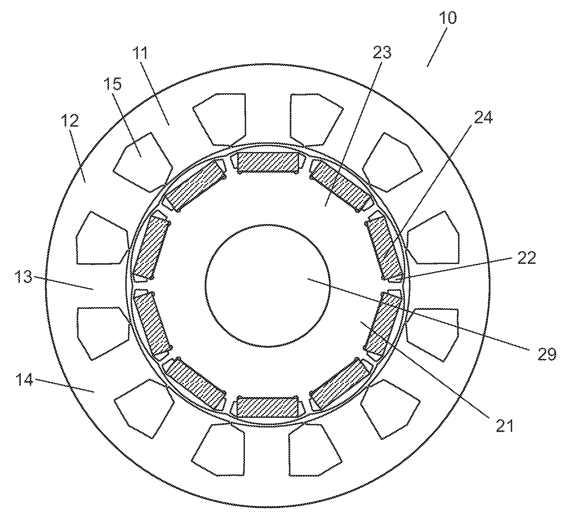
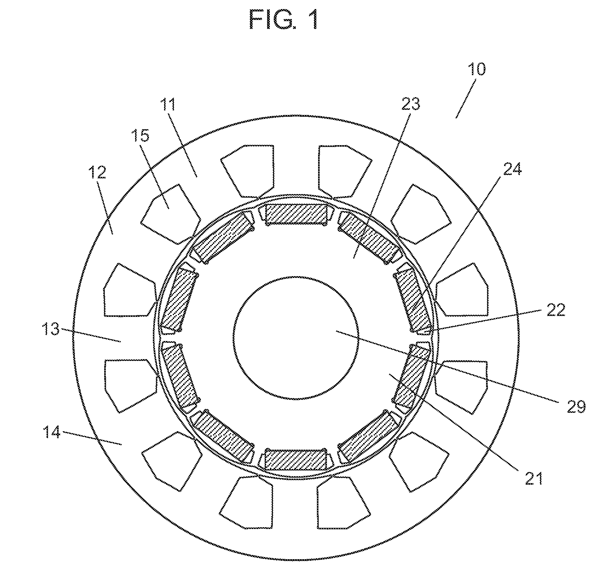
[0021]FIG. 1 is a cross sectional view taken along a plane perpendicular to a center axis of rotation of permanent-magnet-embedded electric motor 10 according to the exemplary embodiment of this invention.

[0022]Electric motor 10 according to this embodiment is provided with stator 11 and rotor 21. Stator 11 includes stator core 14 made by laminating a plurality of thin steel plates, and a coil (not shown) wound on stator core 14. Stator core 14 has yoke 12, a plurality of teeth 13 formed along an inner circumference side of yoke 12, and a plurality of slots 15, each formed between adjoining teeth 13. The coil is wound on stator core 14 into either concentrated winding or distributed winding, and placed in slots 15.

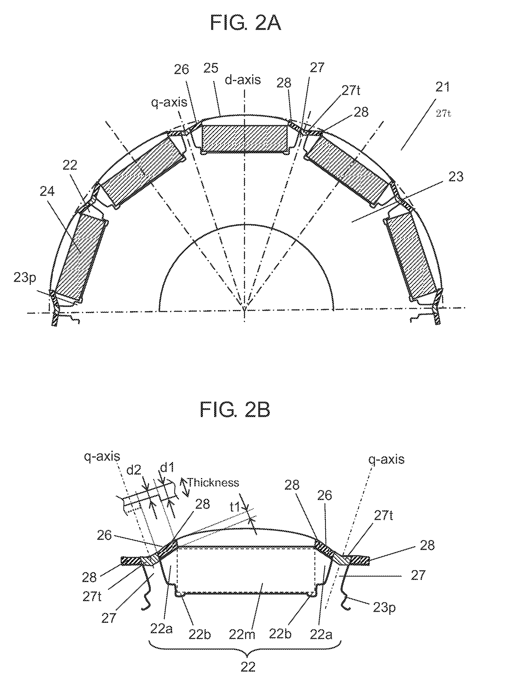
[0023]Rotor 21 includes rotor c...


PUM


Abstract

A permanent-magnet-embedded electric motor includes a stator having a coil wound on a stator core, and a rotor disposed rotatably inside the stator through a gap to an inner circumferential surface of the stator core. The rotor is provided with a rotor core formed of laminated steel plates having a plurality of magnet-embedding holes, and a permanent magnet housed and retained in each of the magnet-embedding holes. A thickness of the bridge portions formed between edges of the magnet-embedding holes and an outer circumference of the rotor core, and a thickness of a thinned link portion connecting adjoining two of the bridge portions are thinner than a thickness of the steel plates.

Description

TECHNICAL FIELD[0001]The present invention relates to a permanent-magnet-embedded electric motor having a permanent-magnet-embedded rotor constructed of a plurality of permanent magnets embedded in a rotor core at predetermined intervals, and the invention also relates to a method for manufacturing the same.BACKGROUND ART[0002]Certain arts such as those described in Patent Literatures 1 and 2 have been known in this technical field.[0003]Patent Literature 1 discloses a rotor having a rotor core of approximately cylindrical shape with a plurality of permanent magnet holes formed in a circumferential direction, and permanent magnets disposed into a shape of letter V in each of the magnet holes, wherein a thickness in an axial direction of a bridge portion formed between an outer edge in a radial direction of each of the magnet holes and an outer circumference is thinner than other parts.[0004]Patent Literature 2 discloses a rotor core steel plate provided with a magnet slot that house...

Claims


Application Information

Patent Timeline
Patent Type & Authority Applications(United States)
IPC IPC(8): H02K1/27H02K1/02H02K3/12H02K15/03H02K1/14H02K1/16
CPCH02K1/2706H02K1/14H02K1/02H02K3/12H02K15/03H02K1/16H02K1/276H02K2213/03
Inventor KAWAMURA, KIYOMIKAWASAKI, HIROAKIYOSHIKAWA, YUICHIKATO, YASUSHIKADO, HARUHIKOASO, NORITAKA
Owner PANASONIC INTELLECTUAL PROPERTY MANAGEMENT CO LTD
Why Eureka
Try Eureka