
Wind power generation system and control method thereof

a wind power generation system and wind power technology, applied in the direction of electric generator control, machines/engines, mechanical equipment, etc., can solve the problems of low power generation efficiency, high manufacturing cost of the full power generator module, and high cost of the full power generator and the full power converter

Active Publication Date: 2016-09-29
DELTA ELECTRONICS INC
View PDF12 Cites 18 Cited by
  • Summary
  • Abstract
  • Description
  • Claims
  • Application Information

AI Technical Summary

Benefits of technology

The patent text describes a wind power generation system that includes doubly-fed wind power generation modules. These modules have a simpler design and lower cost than full power generators, but they have lower efficiency at low wind speeds and are limited by the speed of the generator. This limits their operation range. The technical effect of this patent is to provide an improved design for the doubly-fed wind power generation modules that can increase efficiency and expand the range of wind speeds they can operate within.

Problems solved by technology

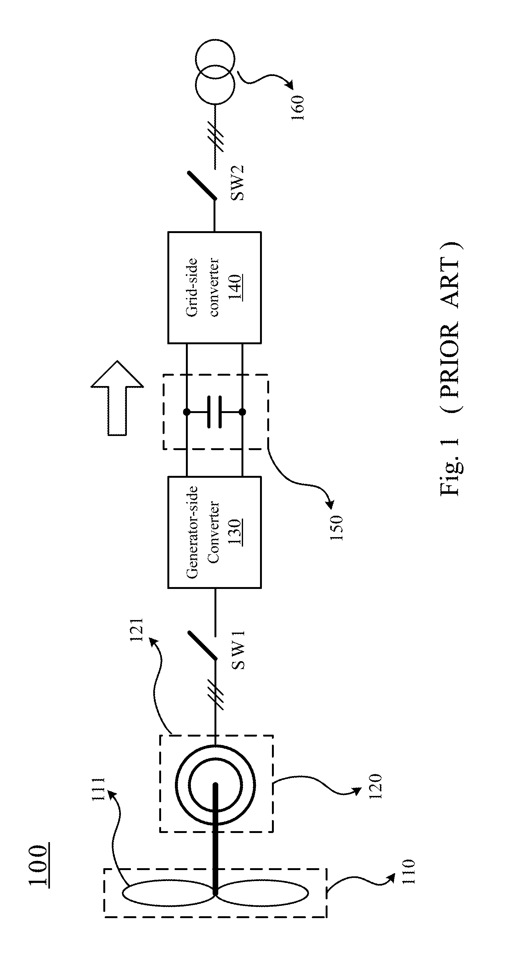
However, since the cost of the full power generator and the full power converter is high (the generator-side converter 130 and the grid-side converter 140 use the converter of large capacity), the manufacturing cost of the full power generator module is high.
However, the disadvantage of the doubly-fed wind power generation modules includes the low efficiency of the power generation under a low wind speed, a greater loss under the low rotation speed and the limited voltage endurance of the electronic components in the converters due to the range of the rotation speed of the generator that results in a limited operation range.

Method used


Image

  • Wind power generation system and control method thereof
  • Wind power generation system and control method thereof
  • Wind power generation system and control method thereof

Examples


Embodiment Construction

[0030]For the embodiment below is described in detail with the accompanying drawings, embodiments are not provided to limit the scope of the present invention. Moreover, the operation of the described structure is not for limiting the order of implementation. Any device with equivalent functions that is produced from a structure formed by a recombination of elements is all covered by the scope of the invention. Drawings are for the purpose of illustration only, and not plotted in accordance with the original size.

[0031]As used herein, the terms “first”, “second” and the like, etc., are used to describe various elements, components, regions, layers and / or blocks can be understood. However, these elements, components, regions, layers and / or blocks should not be limited by these terms. The terms are used to identify a single element. Therefore, in the following a first element, component, region, layer, and / or blocks may also be termed a second element, component, region, layer, and / or...


PUM


Abstract

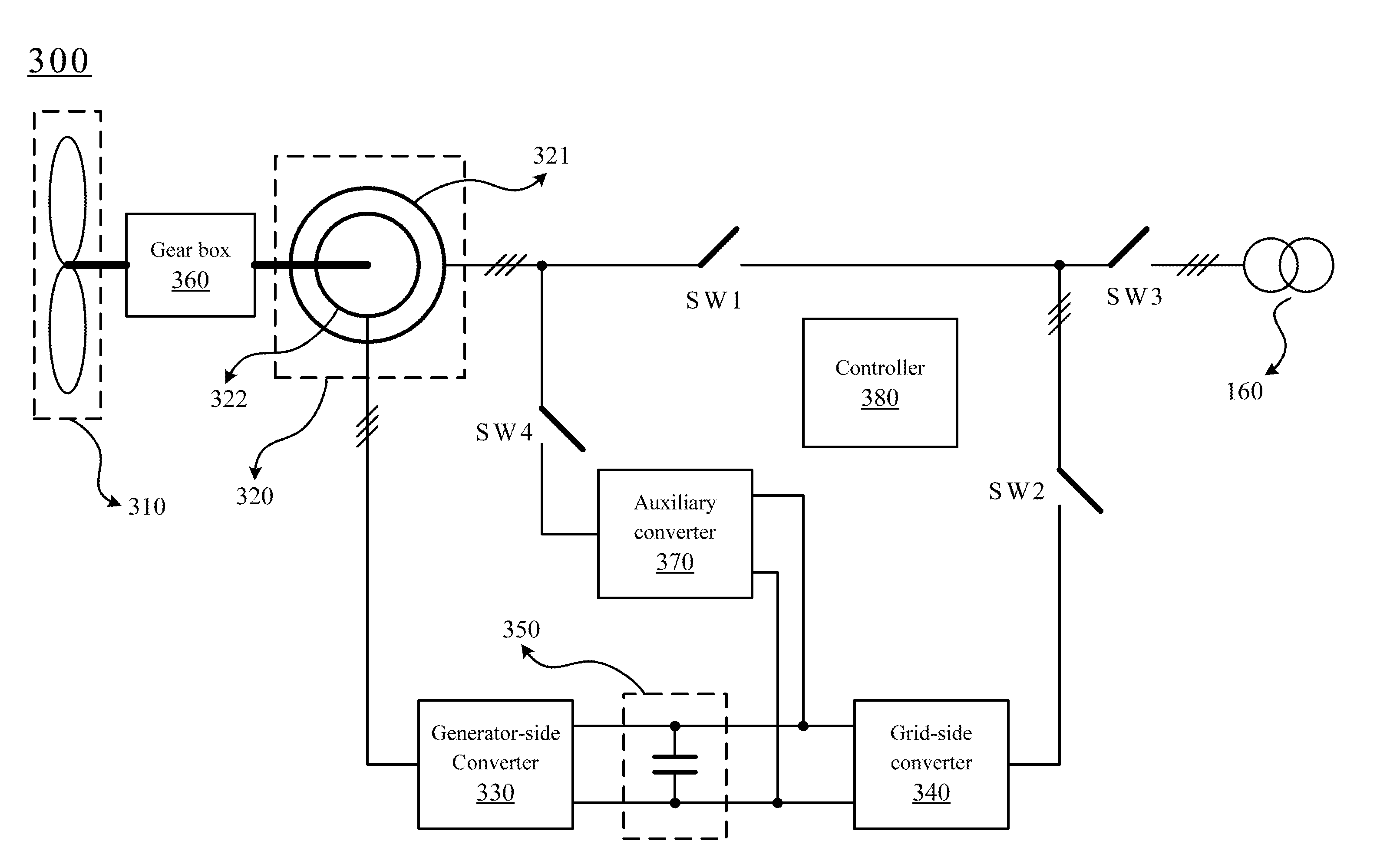
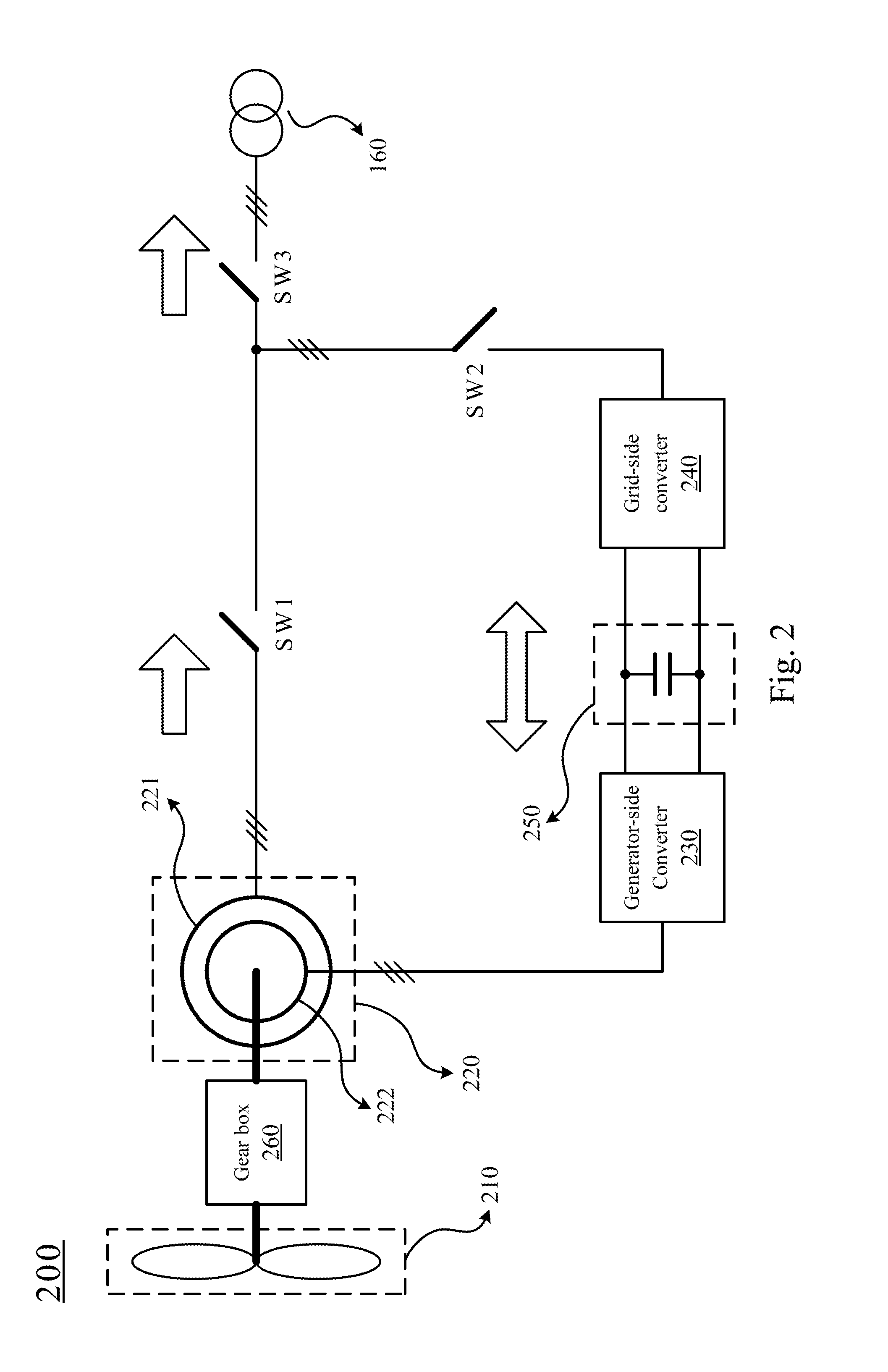
A wind power generation system and a control method thereof are provided herein. The wind power generation system includes a doubly-fed generator, a generator-side converter, a grid-side converter and an auxiliary converter. The doubly fed generator includes a stator winding and a rotor winding. The stator winding is coupled to a grid. The generator-side converter is coupled to the rotor winding. The grid-side converter is coupled between the generator-side converter and the gird. The auxiliary converter includes a first side and a second side. The first side is coupled to the stator winding. The second side is coupled between the generator-side converter and the grid-side converter. The generator-side converter, the grid-side converter and the auxiliary converter use the same DC bus.

Description

RELATED APPLICATIONS[0001]This application claims priority to China Application Serial Number 201510130431.4, filed Mar. 24, 2015, which is herein incorporated by reference.BACKGROUND[0002]1. Field of Disclosure[0003]The present disclosure relates to a wind power generation system. More particularly, the present disclosure relates to a doubly-fed wind power generation system.[0004]2. Description of Related Art[0005]In recent years, the wind power generation technology uses the electronic converter (such as the alternating-current / direct-current / alternating-current converter in combination with a high level control system) such that the grid frequency and the mechanical rotor frequency can be decoupled. The wind power generator module can therefore be operated under variable speed. As a result, the improvement of the variable speed wind power generator module is obvious in recent years.[0006]Mega-watts wind power generation systems can be categorized into full power wind power genera...

Claims


Application Information

Patent Timeline
IPC IPC(8): H02P9/00F03D7/00F03D9/00
CPCH02P9/007F03D7/00F03D9/003F03D7/0272F03D9/255F05B2270/32Y02E10/72
Inventor WANG, CHANG-YONGLU, FEIXUE, HAI-FENCHEN, LICAO, LIANG
Owner DELTA ELECTRONICS INC
Learn More