Air conditioning device

Active Publication Date: 2016-10-06
DENSO CORP
View PDF13 Cites 28 Cited by
  • Summary
  • Abstract
  • Description
  • Claims
  • Application Information

AI Technical Summary

Benefits of technology

[0023]However, according to the third aspect, when viewed from a rotation axis direction of the rotary blower fan, an angle from the suction side virtual line segment to the blowing side virtual line segment in the rotation direction of the rotary blower fan is smaller than an angle from the suction side virtual line segment to the blowing side virtual line segment in an o

Problems solved by technology

The actuating device may increase the deviation between the position of the suction side partitioning member and the position of the blowing side part

Method used


Image

  • Air conditioning device
  • Air conditioning device
  • Air conditioning device

Examples


first embodiment

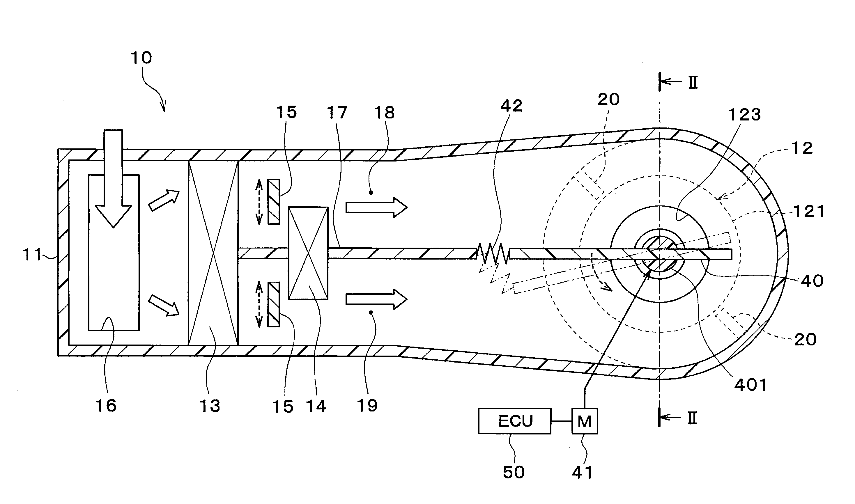
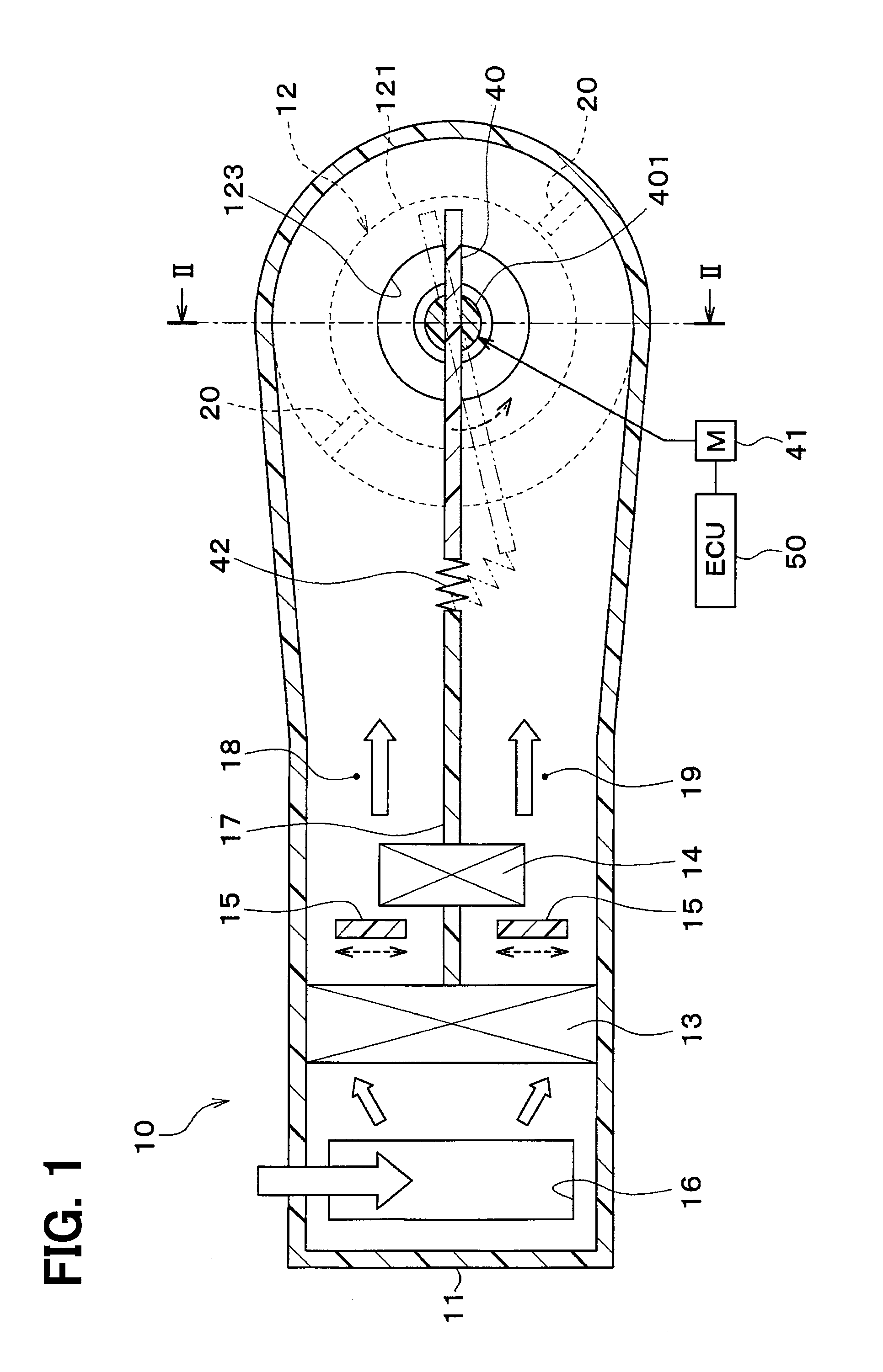
[0059]Subsequently, a detailed configuration of a vehicle air conditioning device 1 according to the present embodiment will be described with reference to FIGS. 1 to 4. As illustrated in FIG. 1, the vehicle air conditioning device 1 includes an interior air conditioning unit 10. The interior air conditioning unit 10 has a function of adjusting a temperature of a blown air and blowing the air into a vehicle interior (space to be air-conditioned).

[0060]The interior air conditioning unit 10 is disposed inside of a dashboard panel (instrument panel) on a foremost portion of the vehicle interior. The interior air conditioning unit 10 includes a casing 11, a blower 12, an evaporator 13, a heater core 14, and air mix doors 15.

[0061]The casing 11 forms an outer shell of the interior air conditioning unit 10. The blower 12, the evaporator 13, the heater core 14, and the air mix doors 15 are housed in the casing 11.

[0062]The casing 11 defines an air passage of the blown air which is blown in...

second embodiment

[0117]In the above embodiment, the position of each blowing side partitioning member 20 is fixed, and the position of each suction side partitioning member 40 is changed. On the other hand, in the present embodiment, as illustrated in FIG. 5, contrary to the above embodiment, a position of each suction side partitioning member 40 is fixed, and a position of each blowing side partitioning member 20 is changed.

[0118]The blowing side partitioning members 20 are driven in a circumferential direction of a blower fan 121 by an electric actuator (not illustrated). The operation of the electric actuator for the blowing side partitioning members 20 is controlled according to a control signal output from an air-conditioning control device 50.

[0119]The air-conditioning control device 50 controls the electric actuator for the blowing side partitioning members 20 according to a pressure loss of an overall air passage in an air conditioning device. Specifically, the air-conditioning control devic...

third embodiment

[0121]In the above embodiments, the air mix doors 15 and the suction side partitioning members 40 are provided, separately. On the other hand, in the present embodiment, as illustrated in FIGS. 6 to 8, each air mix door 15 is disposed integrally with a corresponding suction side partitioning member 40.

[0122]As illustrated in FIGS. 6 and 7, in the present embodiment, a casing 11 is formed into a cylindrical shape. An inside air inlet port 16a and an outside air inlet port 16b are defined in an outermost periphery of the casing 11. Opening areas of the inside air inlet port and the outside air inlet port are continuously adjusted by an inside and outside air switching door 16c.

[0123]An evaporator 13 is cylindrically disposed inside of the casing 11. A heater core 14 is cylindrically disposed inside of the evaporator 13 in the interior of the casing 11. The evaporator 13 and the heater core 14 are disposed coaxially with the casing 11.

[0124]The suction side partitioning members 40 are...


PUM


Abstract

An air conditioning device includes a casing that provides multiple air passages, a blower fan that suctions an air from the multiple air passages and blows out the air in the casing, a suction side partitioning member that is disposed on a suction side of the blower fan in the casing and separates air flows from the multiple air passages from each other, and a blowing side partitioning member that is disposed on a blowing side of the blower fan in the casing and separates the air flows from the multiple air passages from each other. The suction side partitioning member and the blowing side partitioning member are disposed so that a relative position of the blowing side partitioning member to the suction side partitioning member is deviated in a rotation direction of the blower fan.

Description

CROSS REFERENCE TO RELATED APPLICATION[0001]This application is based on and incorporates herein by reference Japanese Patent Applications No. 2013-239601 filed on Nov. 20, 2013, No. 2014-116789 filed on Jun. 5, 2014, and No. 2014-191317 filed on Sep. 19, 2014.TECHNICAL FIELD[0002]The present disclosure relates to an air conditioning device having a blower fan.BACKGROUND ART[0003]Up to now, Patent Documents 1 and 2 disclose an air conditioning device having a layout in which a blower fan is disposed on an air flow downstream side of a heat exchanger within an air conditioning duct.[0004]In the conventional art, an air conditioning wind that has been adjusted in temperature by the heat exchanger within an air conditioning duct is suctioned into the blower fan, and blown out in a radial direction, and the air conditioning wind blown out of the blower fan in the radial direction is blown out from a blowing port of the air conditioning duct.[0005]In the conventional art disclosed in Pat...

Claims


Application Information

Patent Timeline
IPC IPC(8): B60H1/00
CPCB60H1/00064B60H1/00471B60H1/00678B60H2001/00721B60H2001/00092B60H2001/00135B60H2001/00192B60H1/00564B60H1/00021B60H2001/00085F24F1/0018
Inventor YAMAOKA, JUNKATO, SHINYASEKITO, YASUHIROMAEDA, KENICHIROISHIGURO, SYUNSUKE
Owner DENSO CORP
Why Eureka
Try Eureka