

Chain tensioner and relief valve unit
a technology of relief valve and chain tensioner, which is applied in the direction of valve housing, gearing, functional valve types, etc., can solve the problems of increasing the amount of oil consumed, and increasing so as to reduce the number of assembling steps, reduce the amount of oil flowing out to the outside, and reduce the number of parts to be machined
- Summary
- Abstract
- Description
- Claims
- Application Information
AI Technical Summary
Benefits of technology
Problems solved by technology
Method used
Image

Examples
embodiment 1
[0049]A chain tensioner 100 and a relief valve unit 160 according to a first embodiment of the present invention will be described with reference to the drawings.
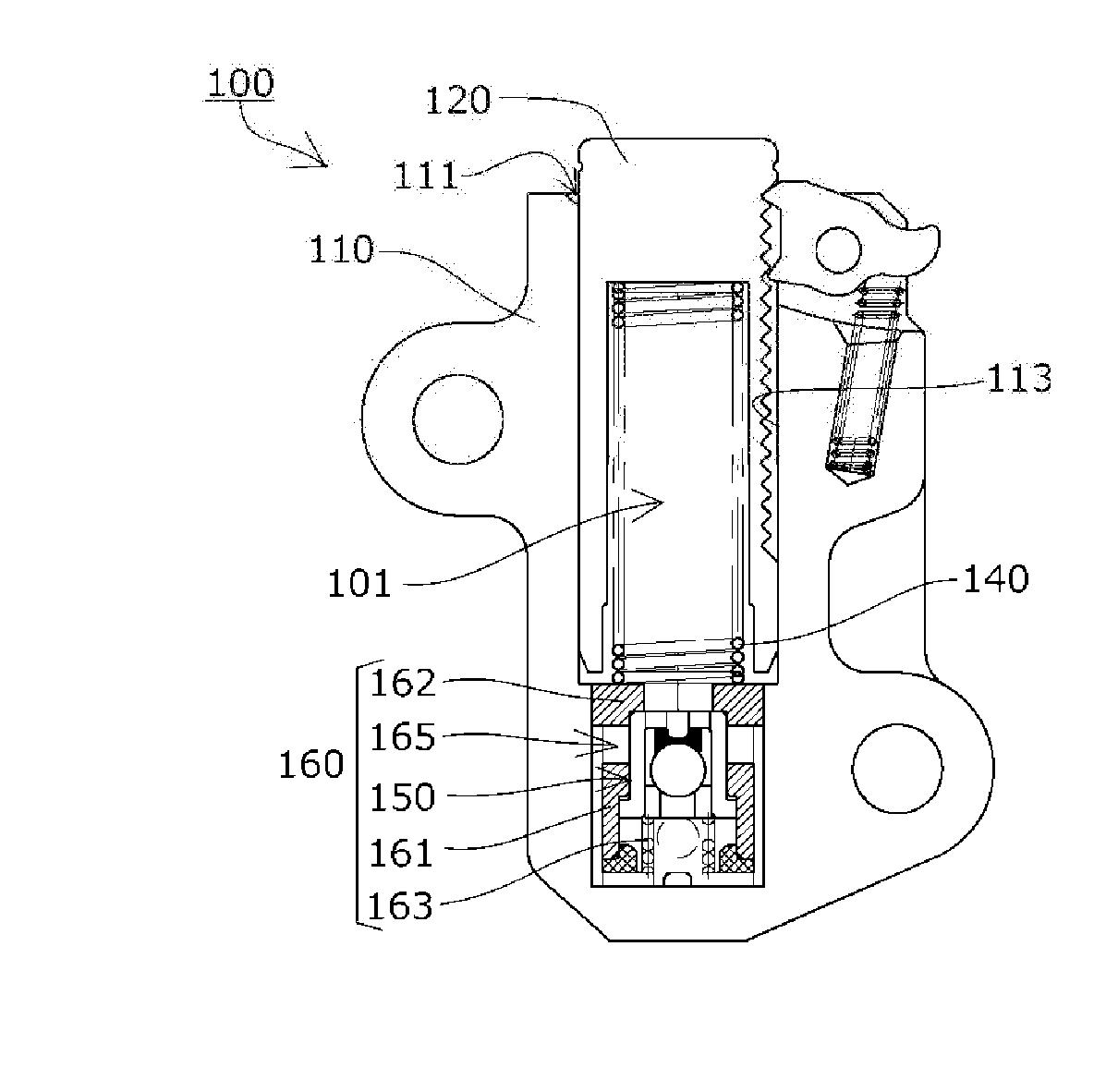
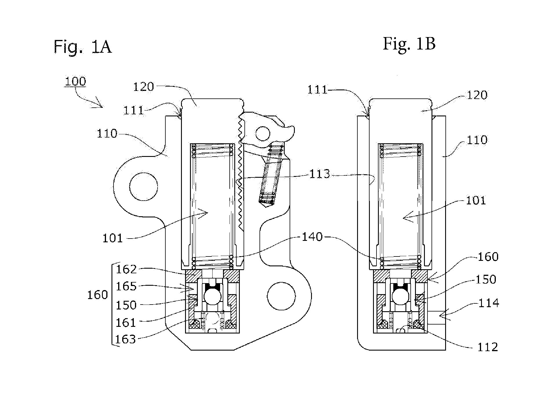
[0050]The chain tensioner 100 according to a first embodiment of the present invention includes, as shown in FIG. 1A and FIG. 1B, a tensioner body 110 that has a cylindrical plunger bore 111 with an open end, a cylindrical plunger 120 that is slidably inserted into the plunger bore 111, and a coil spring 140 that is biasing means, accommodated to freely expand and contract inside an oil pressure chamber 101 formed between the plunger bore 111 and the plunger 120, for biasing the plunger 120 in a protruding direction of the plunger 120.
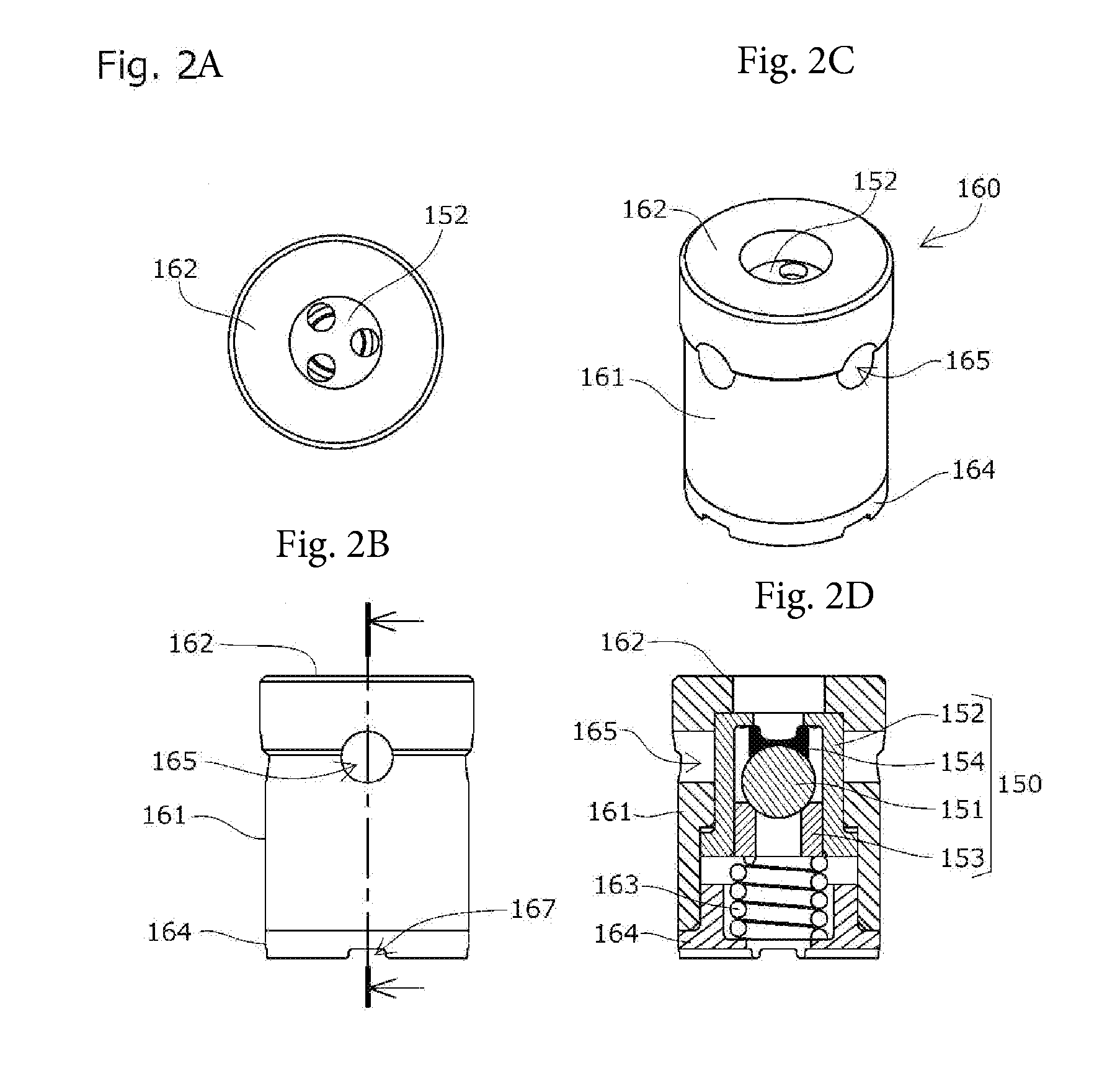
[0051]A relief valve unit 160 is provided at the bottom 112 of the plunger bore 111 of the tensioner body 110, and an oil supply hole 114 is provided near the bottom 112.
[0052]The chain tensioner 100 according to this embodiment is a type known as a ratchet tensioner, which includes a ratchet ...
embodiment 2
[0073]A chain tensioner 200 and a relief valve unit 260 according to a second embodiment of the present invention will be described with reference to the drawings.
[0074]The plunger 220 of the chain tensioner 200 has an oil reservoir chamber 223 inside, as shown in FIG. 3A and FIG. 3B, which is communicated with the oil supply hole 214 via a supply passage 222 and a plunger hole 221. The relief valve unit 260 is disposed inside the oil reservoir chamber 223, and an oil passage 224 is formed between the outer circumference of the relief sleeve 261 and the inner circumference of the plunger 220 for causing released oil to circulate back to the oil reservoir chamber 223.
[0075]The relief valve unit 260 is formed to extend over the entirety of the oil reservoir chamber 223 as shown in FIG. 4A to FIG. 4D and configured similarly to the relief valve unit 160 according to the first embodiment (with reference numerals starting with number 2 as the hundred's digit).
[0076]This relief valve unit...
embodiment 3
[0089]A chain tensioner 300 according to a third embodiment of the present invention will be described with reference to the drawings.
[0090]The chain tensioner 300 according to the third embodiment of the present invention includes, as shown in FIG. 6A and FIG. 6B, similarly to the first embodiment, a tensioner body 310 having a cylindrical plunger bore 311 with an open end, a cylindrical plunger 320 slidably inserted in the plunger bore 311, and a coil spring 340 that is biasing means, accommodated so as to freely expand and contract inside an oil pressure chamber 301 formed between the plunger bore 311 and the plunger 320, for biasing the plunger 320 in the protruding direction of the plunger.
[0091]The same relief valve unit 260 as that of the second embodiment shown in FIG. 4A to FIG. 4D is disposed inside the plunger bore 311 of the tensioner body 310 such as to be slidable into the plunger 320 from the bottom 312, with the relief valve seat 262 of the relief valve unit being or...
PUM
 Abstract
Description
Claims
Application Information