Dual duty microchannel heat exchanger

a heat exchanger and microchannel technology, applied in the field of heat exchangers, can solve the problem of significantly increasing the cost of the assembly

Active Publication Date: 2016-10-06
CARRIER CORP
View PDF12 Cites 25 Cited by
  • Summary
  • Abstract
  • Description
  • Claims
  • Application Information

AI Technical Summary

Problems solved by technology

As a result, the increased design complexity, additional components and installation time required to assemble and integrate the heat exchangers into the system increase the cost of the assembly significantly.

Method used


Image

  • Dual duty microchannel heat exchanger
  • Dual duty microchannel heat exchanger
  • Dual duty microchannel heat exchanger

Examples


Embodiment Construction

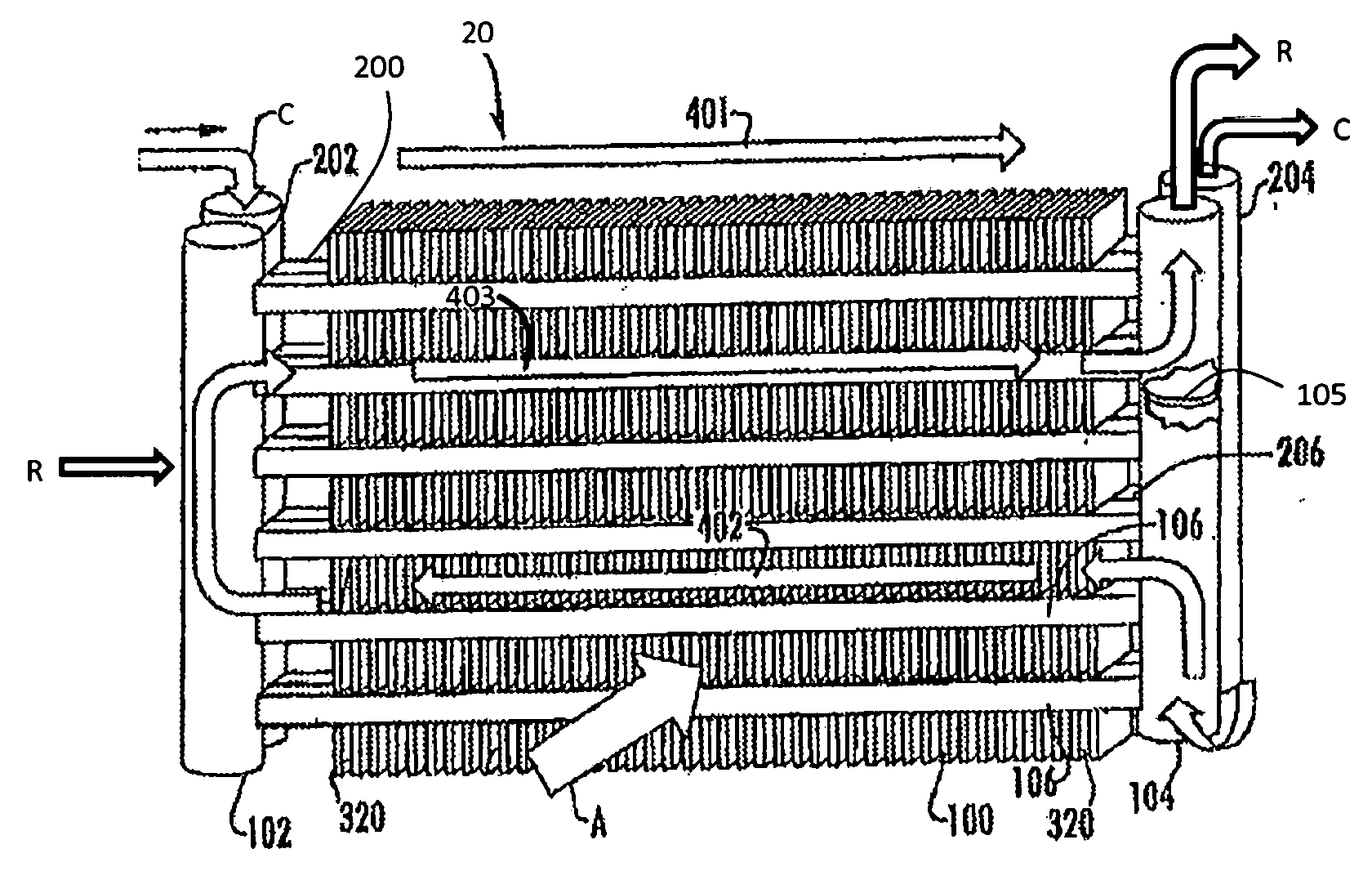
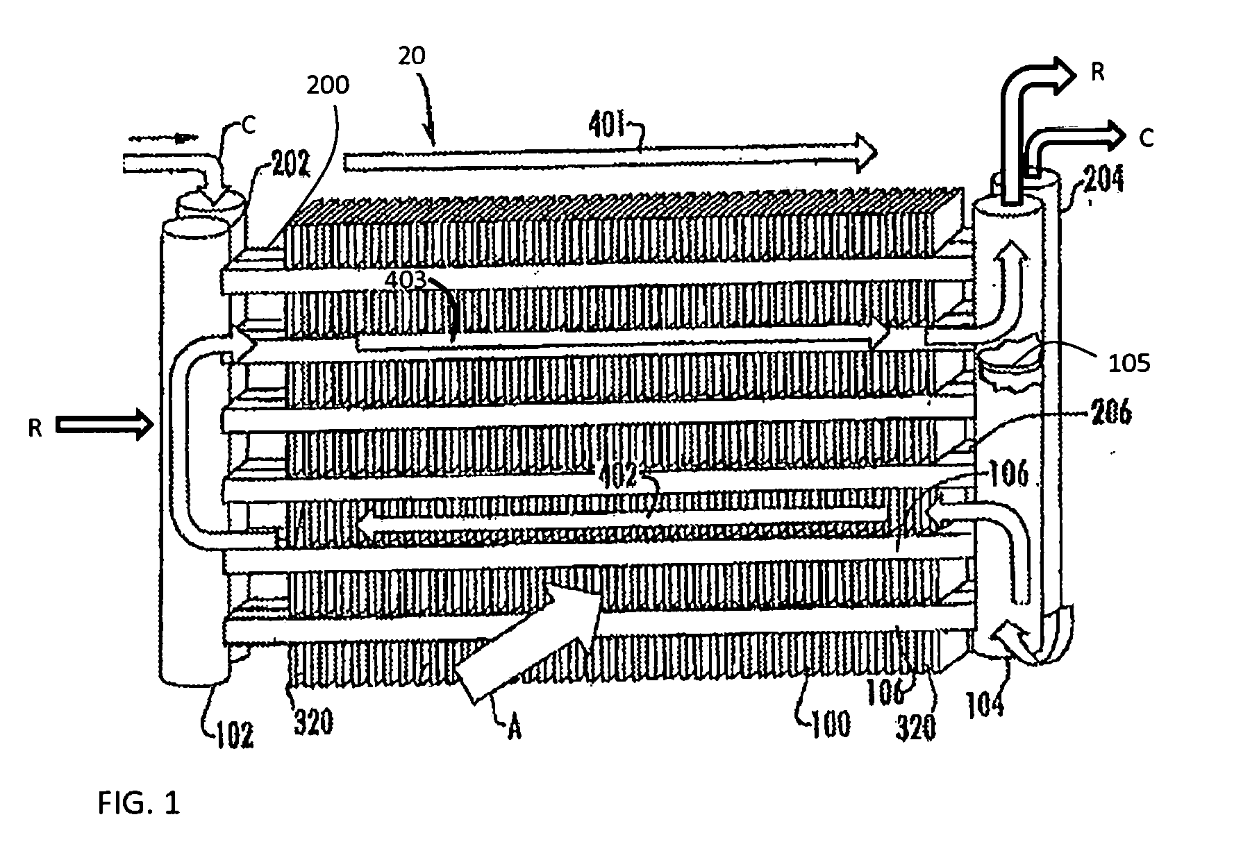
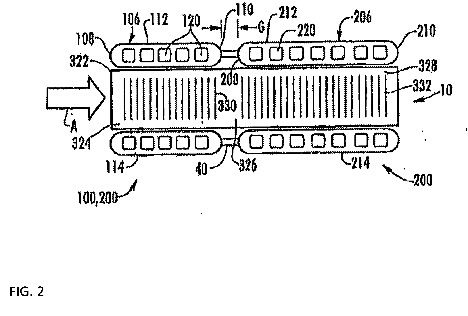
[0019]Referring now to FIGS. 1-4 an example of a multiple bank flattened tube finned heat exchanger configured to receive at least two fluids is shown. In the illustrated, non-limiting embodiment, the heat exchanger 20 includes a first tube bank 100 and a second tube bank 200. The second tube bank 200 is disposed behind the first tube bank 100 and is downstream with respect to an airflow, A, through the heat exchanger 20. The first tube bank 100 may also be referred to herein as the front heat exchanger slab 100 and the second tube bank 200 may also be referred to herein as the rear heat exchanger slab 200. Although the multi-bank heat exchanger 20 illustrated and described herein includes a first and second tube bank 100, 200, a heat exchanger 20 having any number of tube banks is within the scope of the invention.

[0020]The first tube bank 100, illustrated in FIGS. 3 and 3a, includes a first manifold 102, a second manifold 104 spaced apart from the first manifold 102, and a plurali...


PUM


Abstract

A heat exchanger includes a first tube bank having at least a first and a second flattened tube segments extending longitudinally in spaced parallel relationship. A second tube bank includes at least a first group of flattened tube segments and a second group of flattened tube segments extending longitudinally in spaced parallel relationship. The second tube bank is disposed behind the first tube bank with a leading edge of the second tube bank spaced from a trailing edge of the first tube bank. The first group of flattened tube segments is configured to receive a first fluid. The second group of flattened tube segments is configured to receive a second fluid. A fan provides an airflow across the first tube bunk and the second tube bank sequentially.

Description

CROSS-REFERENCE TO RELATED APPLICATION[0001]This application claims the benefit of U.S. provisional patent application Ser. No. 61 / 908,265 filed Nov. 25, 2013, the entire contents of which are incorporated herein by reference.BACKGROUND[0002]This invention relates generally to heat exchangers and, more particularly, to dual duty multiple tube bank heat exchanger for use in heating, ventilation, air conditioning and refrigeration (HVAC&R) systems.[0003]Refrigerant vapor compression systems are well known in the art. Air conditioners and heat pumps employing refrigerant vapor compression cycles are commonly used for cooling or cooling / heating air supplied to a climate-controlled comfort zone within a residence, office building, hospital, school, restaurant or other facility. Refrigerant vapor compression systems are also commonly used for cooling air or other secondary fluid to provide a refrigerated environment for food items and beverage products within, for instance, display cases ...

Claims


Application Information

Patent Timeline
Patent Type & Authority Applications(United States)
IPC IPC(8): F28D7/00F28F1/12F25B39/00
CPCF28D7/0091F25B39/00F28F2260/02F28D2021/0068F28F1/126F28D1/0435F28D1/05391F25B39/02F25B39/04F25B40/02F25B40/06
Inventor TARAS, MICHAEL F.
Owner CARRIER CORP
Why Eureka
Try Eureka