3D Balanced EPI Magnetic Resonance Fingerprinting

a magnetic resonance fingerprinting and epi magnetic resonance technology, applied in the field of magnetic resonance imaging systems and methods, can solve the problems of limiting the widespread clinical use of mrf techniques, requiring a complicated image reconstruction algorithm, and not being available on many clinical systems

Active Publication Date: 2016-10-06
THE GENERAL HOSPITAL CORP
View PDF10 Cites 29 Cited by
  • Summary
  • Abstract
  • Description
  • Claims
  • Application Information

AI Technical Summary

Benefits of technology

[0011]In accordance with one aspect of the disclosure, a method is provided for acquiring magnetic resonance fingerprinting (MRF) data from a subject using a magnetic resonance imaging (MRI) system. The method including steps of a) selecting a pulse sequence to perform that samples k-space in a Cartesian acquisition pattern by acquiring an echo train and b) determining acquisition parameters for the pulse sequence, including at least one of repetition time (TR) or flip angle (FA), selected to control one of a duration and a number of repetitions of the pulse sequence. The method also includes c) directing a magnetic resonance imaging (MRI) system to acquire 3-dimensional (3D) magnetic resonance fingerprinting (MRF) data from the subject by performing the pulse sequence and d) directing the MRI system to repeat step c) using varied scan parameters to acquire sets of the 3D MRF data using differing scan parameters, e) estimating quantitative tissue properties of the subject by comparing the sets of the 3D MRF data using differing scan parameters to a database, and f) generate at least one image of the subject indicating the quantitative tissue properties.
[0012]In accordance with another aspect of the disclosure, a magnetic resonance imaging (MRI) system is provided t

Problems solved by technology

This acquisition time is quite lengthy and limits the widespread clinical usage of MRF techniques.
In addition to lengthy acquisition time, MRF using a spiral k-space trajectory requires a complicated algorithm for image reconstruction and is not available on many clinical systems.
Even when supported, the resulting images are plagued by imaging artifacts.
Further, the resulting images do not provide quantitative information about the patient, which is a

Method used


Image

  • 3D Balanced EPI Magnetic Resonance Fingerprinting
  • 3D Balanced EPI Magnetic Resonance Fingerprinting
  • 3D Balanced EPI Magnetic Resonance Fingerprinting

Examples


Embodiment Construction

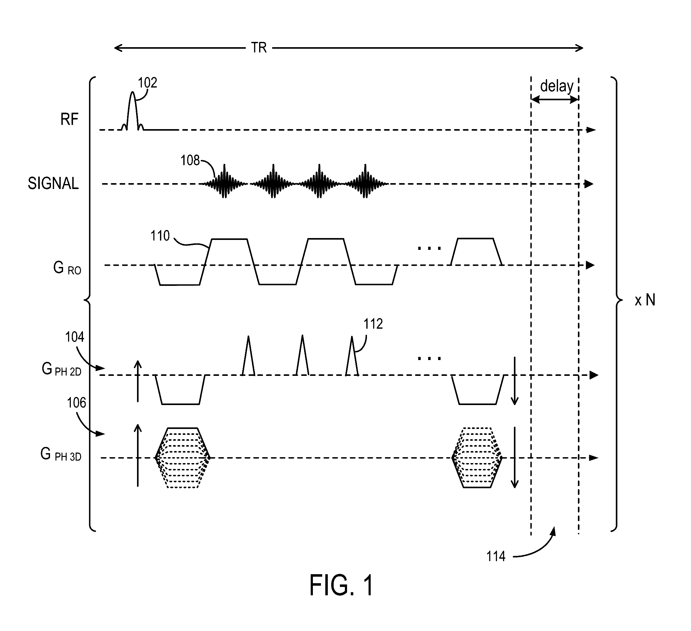
[0024]Described here are systems and methods for implementing Magnetic Resonance Fingerprinting (MRF) using an optimized, fully-refocused 3D balanced-EPI (b-EPI) pulse sequence. The systems and methods may also include implementing pulse sequences that rapidly acquire large volumes of k-space data, including echo-planar imaging (“EPI”) and segmented EPI sequences.

[0025]Referring specifically now to FIG. 1, an example pulse sequence diagram of a modified spin-echo EPI technique for use in accordance with the MRF approach of the present disclosure, is shown. Specifically, for each TR, a selective RF excitation pulse 102 that is coordinated with a 2D phase encoding gradient pulse 104 and a 3D phase encoding gradient pulse 106 are applied to position encode the nuclear magnetic resonance (NMR) signal 108 along one direction in the slice. A series of readout gradient pulses 110 with alternating polarity are played along the readout direction to produce a series of spin-echo signals 108. ...


PUM


Abstract

Provided is a system and method for performing a magnetic resonance fingerprinting imaging process. The process includes determining acquisition parameters including at least one of repetition time (TR) or flip angle (FA), selected to control one of a duration and a number of repetitions of for a pulse sequence that samples k-space in a Cartesian acquisition pattern by acquiring an echo train. The process also includes controlling a magnetic resonance imaging (MRI) system to perform the pulse sequence a plurality of times to acquire magnetic resonance fingerprinting (MRF) data corresponding to signals from the subject excited by the pulse sequence. The process also includes estimating quantitative tissue properties of the subject by comparing the MRF data to a database and reconstructing, from the MRF data, at least one image of the subject indicating the estimated quantitative tissue properties.

Description

CROSS-REFERENCE TO RELATED APPLICATIONS[0001]This application is based on, claims priority to, and incorporates herein by reference in its entirety, U.S. Provisional Application Ser. No. 62 / 142,049, filed Apr. 2, 2015, and entitled “3D BALANCED EPI MAGNETIC RESONANCE FINGERPRINTING.”STATEMENT REGARDING FEDERALLY SPONSORED RESEARCH[0002]This invention was made with government support under W81XWH-11-2-076 awarded by the Department of Defense. The government has certain rights in the invention.BACKGROUND[0003]The present disclosure relates to systems and methods for magnetic resonance imaging (“MRI”). More particularly, the disclosure relates to systems and methods for accelerating data acquisitions used in magnetic resonance fingerprinting applications.[0004]Magnetic resonance fingerprinting (“MRF”) is an imaging technique that enables quantitative mapping of tissue or other material properties based on random or pseudorandom measurements of the subject or object being imaged. Exampl...

Claims


Application Information

Patent Timeline
IPC IPC(8): G01R33/48G01R33/561G01R33/54
CPCG01R33/4828G01R33/482G01R33/5614G01R33/5616G01R33/543G01R33/4835G01R33/50
Inventor ROSEN, MATTHEW S.SARRACANIE, MATHIEUCOHEN, OURI
Owner THE GENERAL HOSPITAL CORP
Why Eureka
Try Eureka