
Method and system for displaying an area

a technology of displaying methods and systems, applied in the direction of measuring devices, using reradiation, instruments, etc., can solve the problems of significant disruption of mining process, loss of lives, equipment damage, etc., and achieve the effect of useful commercial choi

Active Publication Date: 2016-10-06
GROUNDPROBE
View PDF11 Cites 10 Cited by
  • Summary
  • Abstract
  • Description
  • Claims
  • Application Information

AI Technical Summary

Benefits of technology

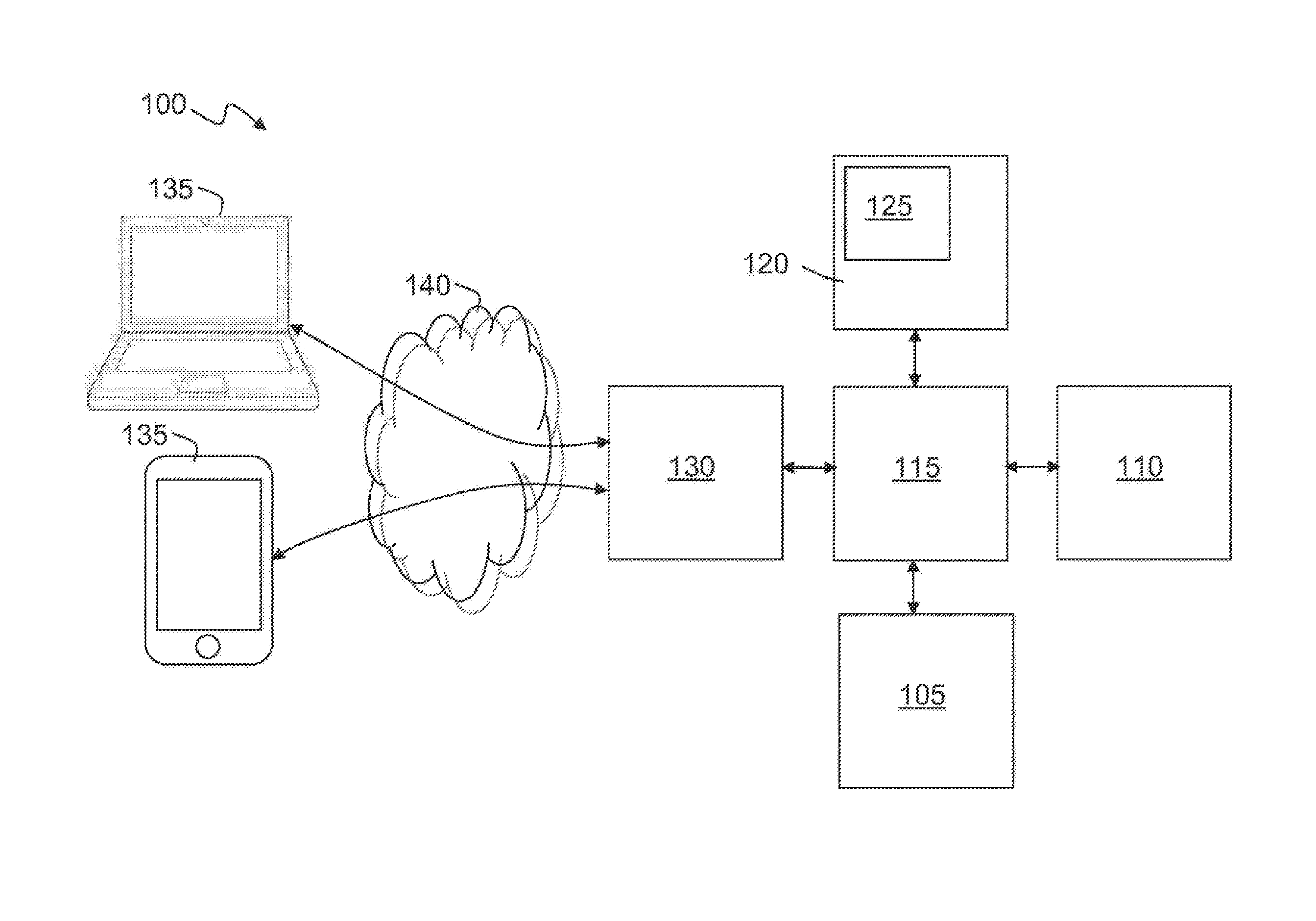
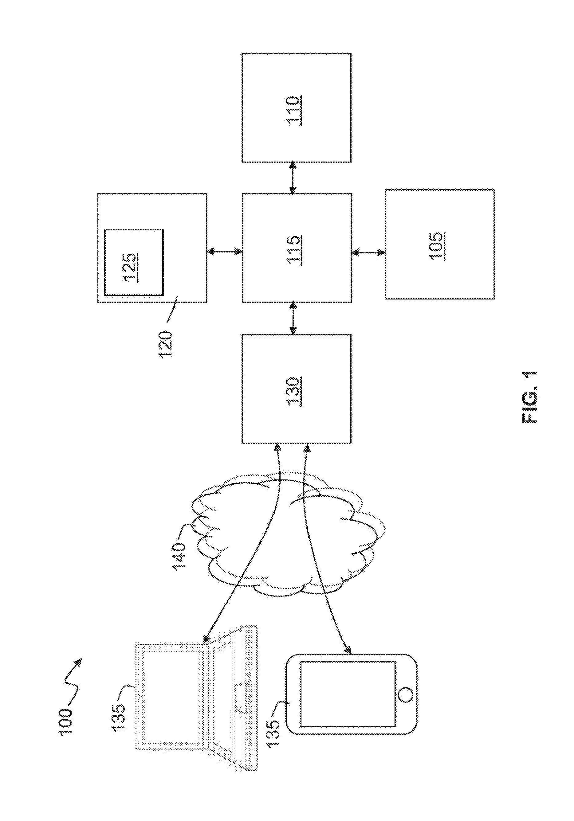
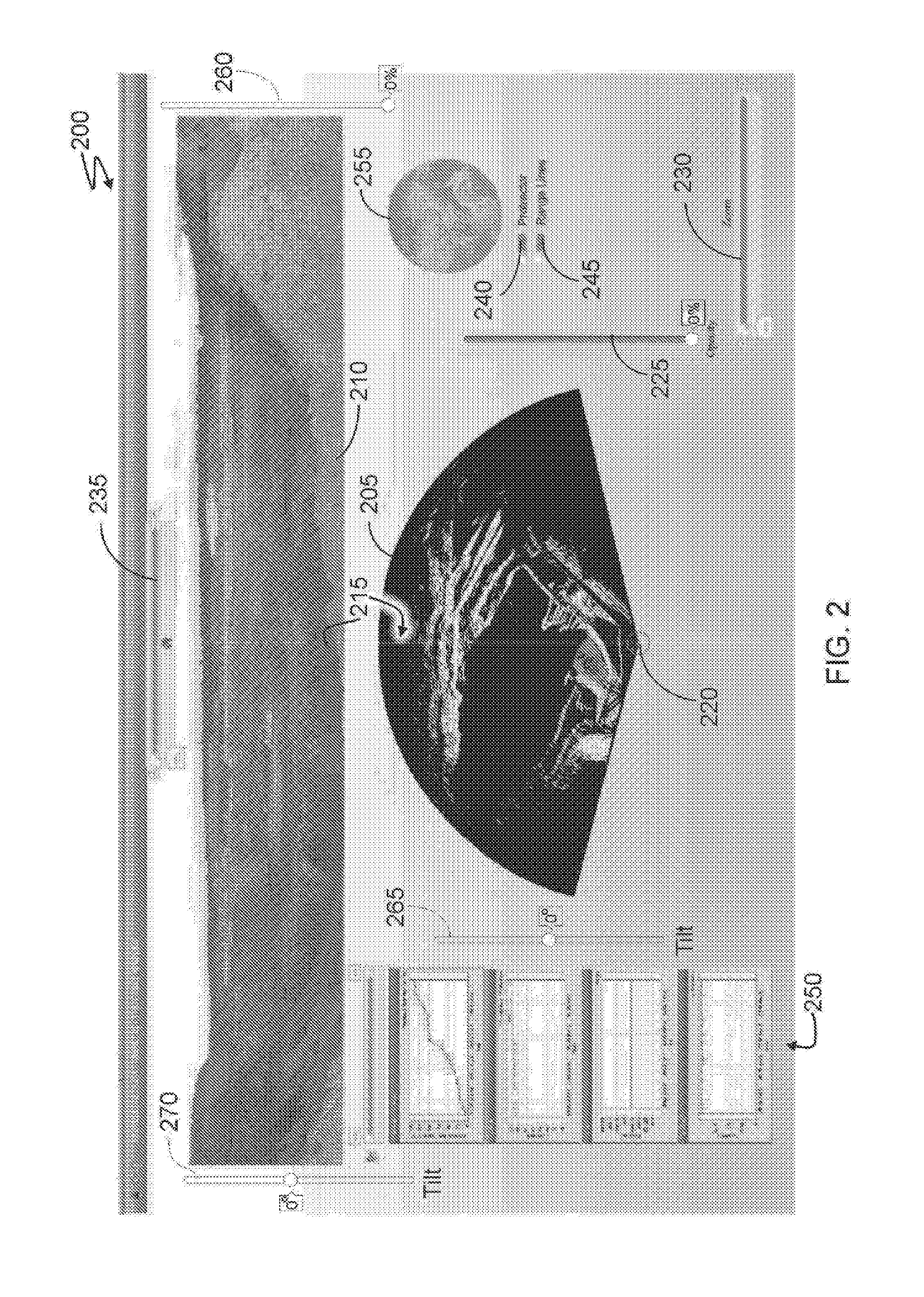
The invention is a method and system for displaying an area using a graphical user interface that includes a front view and a top view of the area. The front view and top view are generated from front view and top view data that is based on a first line-of-sight. The system also allows an operator to interact with the front view and top view, and the interface will update the front view and top view accordingly. The front view and top view may be generated from image data or radar data, and the system may include a camera and a radar for capturing the front view and top view. The technical effects of this invention include improved visual and spatial awareness for the operator and better understanding of the area being displayed.

Problems solved by technology

Slope stability is a critical safety and production issue for open cut mines, quarries, civil engineering works and the like.
Major wall failures can occur seemingly without warning causing loss of lives, damage to equipment, significant disruption to the mining process.
Tell-tale signs of slope instability include the opening of cracks on the wall surface and crest, audible creaking, and increased rilling of spoil.
It is difficult to interpret these signs to be able to distinguish between expected settling of recently excavated ground and events that will lead to catastrophic slope failure.
However, a problem with manual analysis of the prior art is that it can be complex and prone to error.
For example, it can be difficult to interpret radar data in the context of a mine, which can in turn result in either misinformed decisions, or inefficient utilisation of time.
However such systems are complex, and generally do not enable intuitive analysis of data.
As such, these systems are also prone to error.
Such processes are thus often very time consuming.

Method used


Image

  • Method and system for displaying an area
  • Method and system for displaying an area
  • Method and system for displaying an area

Examples


Embodiment Construction

[0070]Embodiments of the present invention comprise methods and systems for mine safety visualisation. Elements of the invention are illustrated in concise outline form in the drawings, showing only those specific details that are necessary to the understanding of the embodiments of the present invention, but so as not to clutter the disclosure with excessive detail that will be obvious to those of ordinary skill in the art in light of the present description.

[0071]In this patent specification, adjectives such as first and second, left and right, front and back, top and bottom, etc., are used solely to define one element or method step from another element or method step without necessarily requiring a specific relative position or sequence that is described by the adjectives. Words such as “comprises” or “includes” are not used to define an exclusive set of elements or method steps. Rather, such words merely define a minimum set of elements or method steps included in a particular ...


PUM


Abstract

A method for displaying an area on a display device, such as a graphical user interface (GUI), by displaying a front view of the area generated from front view data and a top view of the area generated from top view data according to a first line-of-sight; processing an interaction between an operator and one of the front view and the top view of the GUI; and displaying on the same display device an updated front view of the area and an updated top view of the area, wherein the updated front view and the updated top view are generated from the front view data and top view data according to a second line-of-sight, and wherein the first line-of-sight and the second line-of-sight have a common origin. The method is particularly useful for visualising, for example, an open cut mine. An apparatus for working the method is also described.

Description

FIELD OF THE INVENTION[0001]The present invention relates to methods and systems for displaying an area, and in particular, although not exclusively, to methods and systems for displaying data relating to a mine wall.BACKGROUND TO THE INVENTION[0002]Slope stability is a critical safety and production issue for open cut mines, quarries, civil engineering works and the like. Major wall failures can occur seemingly without warning causing loss of lives, damage to equipment, significant disruption to the mining process.[0003]Tell-tale signs of slope instability include the opening of cracks on the wall surface and crest, audible creaking, and increased rilling of spoil. It is difficult to interpret these signs to be able to distinguish between expected settling of recently excavated ground and events that will lead to catastrophic slope failure.[0004]There are various slope monitoring systems employed by mine sites to monitor movement of slopes in order to provide an accurate reflection...

Claims


Application Information

Patent Timeline
Patent Type & Authority Applications(United States)
IPC IPC(8): G01S13/89G01S7/51G01S17/89G01S13/86G01S7/20
CPCG01S13/89G01S13/867G01S7/51G01S17/89G01S7/20G01S7/18G01S7/295G01C11/02
Inventor BELLETT, PATRICK T.NOON, DAVIDCAMPBELL, LACHLAN
Owner GROUNDPROBE
Learn More