Light emitting device with spectral conversion element

a technology of spectral conversion and light emitting device, which is applied in the direction of semiconductor devices for light sources, lighting and heating apparatus, instruments, etc., can solve the problems of reducing the optical performance of both the light guide and leds, and the light guide is heated and the optical performance is reduced, so as to optimize the optical performance and keep the temperature of the light guide relatively low

Active Publication Date: 2016-10-06
SIGNIFY HLDG BV
View PDF2 Cites 9 Cited by
  • Summary
  • Abstract
  • Description
  • Claims
  • Application Information

AI Technical Summary

Benefits of technology

[0008]It is an object of the present invention to overcome this problem, and to provide a light emitting device with which a large amount of light is brought to and coupled into the ...

Problems solved by technology

A problem associated with this configuration is related to bringing enough light to the light guide while keeping the temperature relatively low.
As a result of th...

Method used


Image

  • Light emitting device with spectral conversion element
  • Light emitting device with spectral conversion element
  • Light emitting device with spectral conversion element

Examples


second embodiment

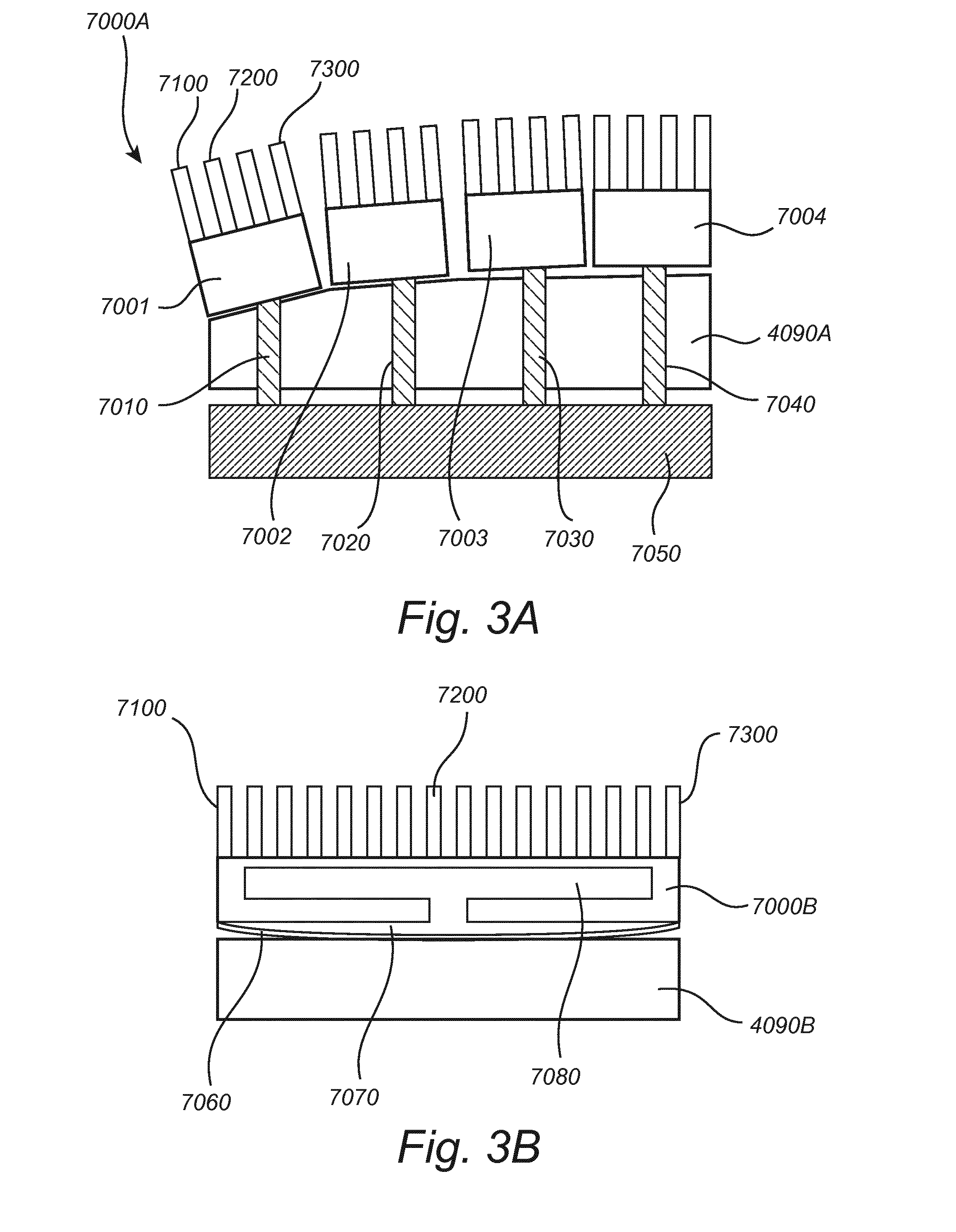
[0112]Turning now to FIG. 6, an end view of a light emitting device 101 according to the invention is shown. The light emitting device 101 differs from that shown in FIG. 4 and described above in that it further comprises a coupling element 80 adapted for coupling light into the at least one luminescent element and a coupling element 9 adapted for coupling light out of the first light guide 3.

[0113]The coupling element 80 is arranged between the first light guide 3 and the luminescent element 90. The coupling element 80 may e.g. be an optical adhesive or it may be a refractive or diffractive grating or scattering layer or structures. Alternatively, the coupling element 80 may simply be air, e.g. in the form of an air gap. Other suitable coupling elements are described above. In an embodiment the coupling element 80 comprises a material chosen such that a third refractive index n3 of the coupling element is smaller than the second refractive index n2 of the luminescent element 90 and...

third embodiment

[0116]FIG. 7 shows an end view of a light emitting device 102 according to the invention. The light emitting device 102 differs from that shown in FIG. 4 and described above in that the first light guide 301 is a shaped light guide comprising two legs or parts 3011 and 3012 each comprising a light input surface 311 and 312, respectively, each associated with a first light source 21 and 24, respectively. The two parts 3011 and 3012 of the first light guide 301 further comprise one common first light exit surface 32, at which the luminescent element90 is provided.

[0117]It is noted that in principle the first light guide 3 may be provided with any feasible shape, the shape shown in FIG. 7 thus being a non-limiting example only.

[0118]Such a configuration provides for light emitting devices which may be shaped according to e.g. aesthetic, physical or practical requirements.

fourth embodiment

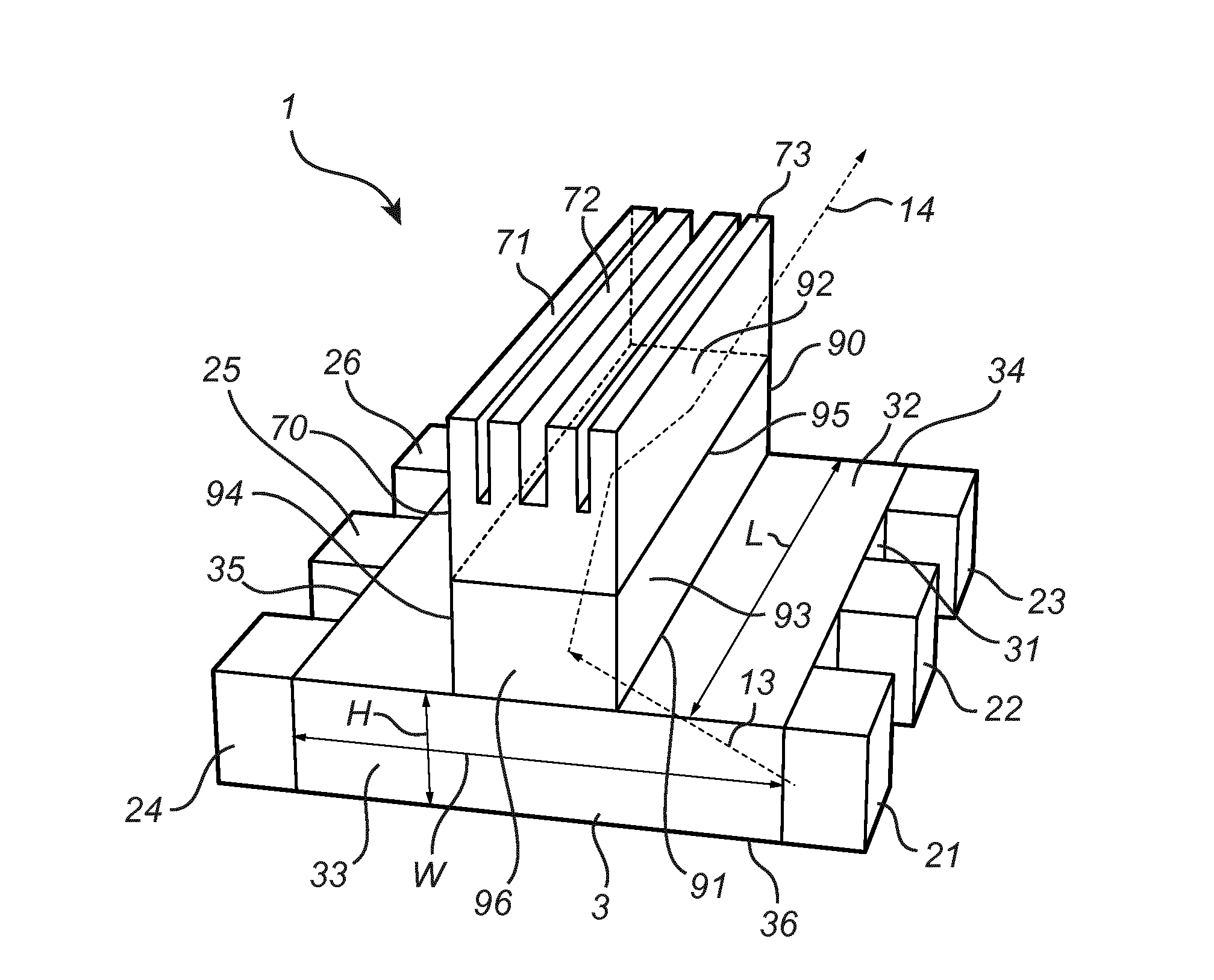
[0119]FIG. 8 shows a top view of a light emitting device 103 according to the invention. For the sake of simplicity the heat sink element has been omitted. The light emitting device 103 differs from that shown in FIG. 4 and described above only in that additional light sources 251, 252, 261, 262 are arranged at the first further surface 33 of the first light guide 3 such that light may be coupled into the light guide from three sides. Thereby the intensity of the light emitted by the light emitting device 103 may be increased compared to the light emitting devices described above.

[0120]Obviously, it would in embodiments of the type shown in FIG. 8 also be feasible to provide light sources on the surface 34 and / or to omit the light sources provided on the surface 35.


PUM


Abstract

A light emitting device comprising at least one first light source (21, 22, 23, 24, 25, 211) adapted for, in operation, emitting first light (13) with a first spectral distribution, a first light guide (3) comprising a first light input surface (31), a first light exit surface (32) and at least one first further surface (33, 34, 35, 36), the first light guide being adapted for receiving the fir with the first spectral distribution at the first light input surface, guiding the first light to the first light exit surface and coupling the first light with the first spectral distribution out of the first light exit surface, at least one luminescent element (90) arranged on the first light exit surface of the first light guide, the at least one luminescent element comprising a second light input surface (91), a second light exit surface (92) and at least one light exit surface (92) and at least one second further surface (93, 94, 95, 96), the luminescent element spectral distribution at the second light input surface, converting at least a part of the first light with the first spectral distribution to second light (14) with a second spectral distribution, guiding the second light to the second light exit surface and coupling the second light with the second spectral distribution out of the second light exit surface, the light emitting device further comprising at least one first heat sink element (70) arranged at or on a surface of the luminescent element facing away from the second light input surface (92).

Description

FIELD OF THE INVENTION[0001]The invention relates to a light emitting device having at least one light source and a light guide. The invention further relates to a lamp, a luminaire or a lighting system comprising such a light emitting device.BACKGROUND OF THE INVENTION[0002]High intensity light sources, and particularly white high intensity light sources, are interesting for various applications including spots, stage-lighting, automotive lighting and digital light projection. For such purposes, as well as for obtaining a desired light shape, light distribution and color distribution with a point of high intensity, it is possible to make use of so-called light concentrators where short wavelength light is converted to longer wavelengths in a highly transparent luminescent material. Such a transparent luminescent material is illuminated by LEDs to produce longer wavelengths within the luminescent material. Converted light, which will be waveguided in the luminescent material, is ext...

Claims


Application Information

Patent Timeline
IPC IPC(8): F21V8/00F21K99/00H01L33/50H01L33/58H01L25/075H01L33/64
CPCG02B6/005H01L25/0753H01L33/644H01L33/642H01L33/507F21K9/56G02B6/0096G02B6/0085G02B6/0055F21K9/52H01L33/58G03B21/204F21V29/502H01L2924/0002F21K9/61F21K9/64H01L2924/00G02B6/00
Inventor HIKMET, RIFAT ATA MUSTAFAVAN BOMMEL, TIESDE BOER, DIRK KORNELIS GERHARDUS
Owner SIGNIFY HLDG BV
Why Eureka
Try Eureka