System for virtual display and method of use

a virtual display and display system technology, applied in the field of systems and methods managing, can solve the problems of increasing construction costs, requiring multiple subtasks, and expensive and time-consuming to correct errors in interdependent subtasks, and achieve the effect of improving the optical display of the bim

Active Publication Date: 2016-10-06
CUMMINGS TIMOTHY A
View PDF5 Cites 56 Cited by
  • Summary
  • Abstract
  • Description
  • Claims
  • Application Information

AI Technical Summary

Benefits of technology

[0014]The described embodiments herein disclose significantly more than an abstract idea including technical advancements in the fields of construction management and data processing, and a transformation of data which is directly related to real world objects

Problems solved by technology

Scheduling of construction projects often requires numerous subtasks.
Hence, correcting errors made in interdependent subtasks is expensive and time consuming because it often delays project completion.
If errors in subtasks are made, then the equipment must be either stored or rescheduled quickly, leading to increased construction costs and delay in project completion.
Any delay in receiving such critical information can effect timely project completion.
However, neither paper drawings nor laptop computers display the information to scale.
Viewing information in this manner is often difficult to do and can lead to dangerous and costly mistakes.
While the BIM has helped coordination of tasks and schedules, it is still not completely satisfactory beca

Method used


Image

  • System for virtual display and method of use
  • System for virtual display and method of use
  • System for virtual display and method of use

Examples


Embodiment Construction

[0047]It will be appreciated by those skilled in the art that aspects of the present disclosure may be illustrated and described in any of a number of patentable classes or contexts including any new and useful process or machine or any new and useful improvement.

[0048]Computer program code for carrying out operations for aspects of the present disclosure may be written in any combination of one or more programming languages, including an object oriented programming language such as Java, C++, C#, .NET, Objective C, Ruby, Python SQL, or other modem and commercially available programming languages.

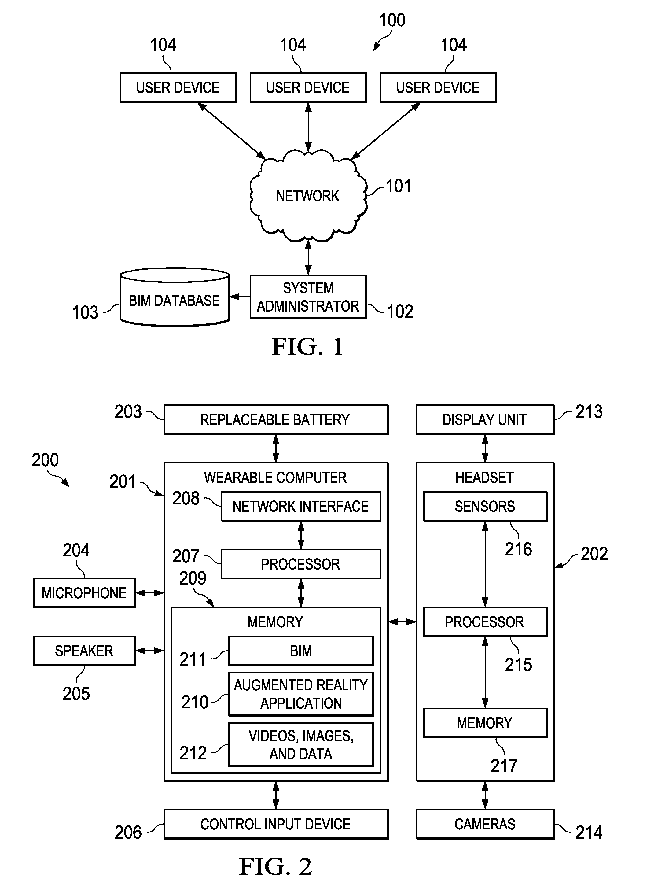
[0049]Referring to FIG. 1, system 100 includes network 101, system administrator 102 connected to network 101, and a set of user devices 104 each of which is connected to network 101. System administrator 102 is further connected to BIM database 103 for storage of relevant data. For example, receiving data may include a business information model, engineering change orders, textual data, eq...


PUM


Abstract

A preferred system and method for projecting a business information model at a construction site includes a network, a system administrator connected to the network, a database connected to the system administrator, a set of registration markers positioned in the construction site, and a set of user devices connected to the network. The system includes a hard hat, a set of headsets mounted to the hard hat, a set of display units movably connected to the set of headsets, a set of cameras connected to the set of headsets, and a wearable computer connected to the set of headsets and to the network. The cameras capture an image of the set of registration markers. A position of the user device is determined from the image and an orientation is determined from motion sensors. A BIM is downloaded and projected to a removable visor based on the position and orientation.

Description

FIELD OF THE INVENTION[0001]The present invention relates to systems and methods managing distribution and use of information at a construction site. In particular, the present invention relates to systems and methods for displaying and using a business information model and other construction information at a construction site. The present invention also relates to virtual display systems, such as heads up displays.BACKGROUND OF THE INVENTION[0002]A major goal of any contractor in the building industry is timely job completion. Hence, efficiency is a paramount concern.[0003]Scheduling of construction projects often requires numerous subtasks. The subtasks are often interdependent. These subtasks must necessarily be completed in order to maximize efficiency. For example, electrical conduit and foundation pads must be in place before installation of electrical equipment can begin. If an error is made in any interdependent subtask, it must be corrected before other tasks can proceed. ...

Claims


Application Information

Patent Timeline
IPC IPC(8): G06T19/00G02B27/01H04N5/247H04N5/225H04N5/232
CPCG06T19/006H04N5/2252H04N5/23238H04N5/247H04N5/2259G02B2027/0138G02B27/0176G02B27/0172G02B27/0179G02B27/0101G02B2027/0123H04N5/23296G02B2027/0181G02B2027/0178G02B2027/0187H04N13/344G01C15/002G06Q50/08G06Q10/067G06Q10/103H04N23/58H04N23/51H04N23/69G01C15/02H04N23/90H04N23/698
Inventor CUMMINGS, TIMOTHY A.HESS, DAVID K.YOUNG, MARVIN R.
Owner CUMMINGS TIMOTHY A
Why Eureka
Try Eureka