Thermal barrier for wireless power transfer

a wireless power transfer and thermal barrier technology, applied in the direction of home appliance efficiency improvement, electric/magnetic/electromagnetic heating, sustainable buildings, etc., can solve the problems of substantial degraded power transfer performance, achieve accurate and efficient control, improve efficiency, and improve the effect of power transfer performan

Active Publication Date: 2016-10-06
KONINKLJIJKE PHILIPS NV
View PDF6 Cites 10 Cited by
  • Summary
  • Abstract
  • Description
  • Claims
  • Application Information

AI Technical Summary

Benefits of technology

[0028]The invention may allow e.g. devices heated by wireless power transfer to be used with wireless power transmitters associated with insufficient thermal protection while at the same time ensuring efficient power transfer.
[0097]This may provide improved functionality and / or operation in many scenarios. In particular, it may reduce the risk of e.g. damage caused by a power receiver supporting a heating function.

Problems solved by technology

In particular, using a conventional thermal barrier will in most scenarios result in a substantially degraded power transfer performance due to the increased distance and reduced coupling between the transmit coil of the power transmitter and the receive element (coil / heating element) of the power receiver.

Method used


Image

  • Thermal barrier for wireless power transfer
  • Thermal barrier for wireless power transfer
  • Thermal barrier for wireless power transfer

Examples


Embodiment Construction

[0119]The following description focuses on embodiments of the invention applicable to a kitchen application, and in particular to a mixed cooking and preparation zone kitchen environment using wireless power transfer. However, it will be appreciated that the invention is not limited to this application but may be applied to many other applications and wireless power transfer systems.

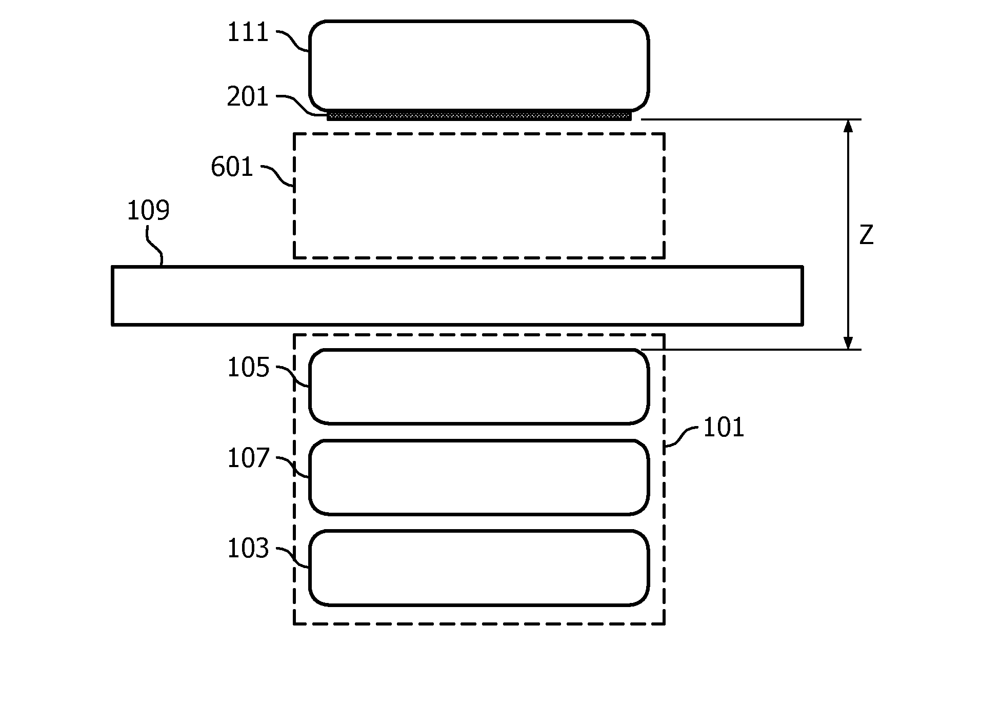
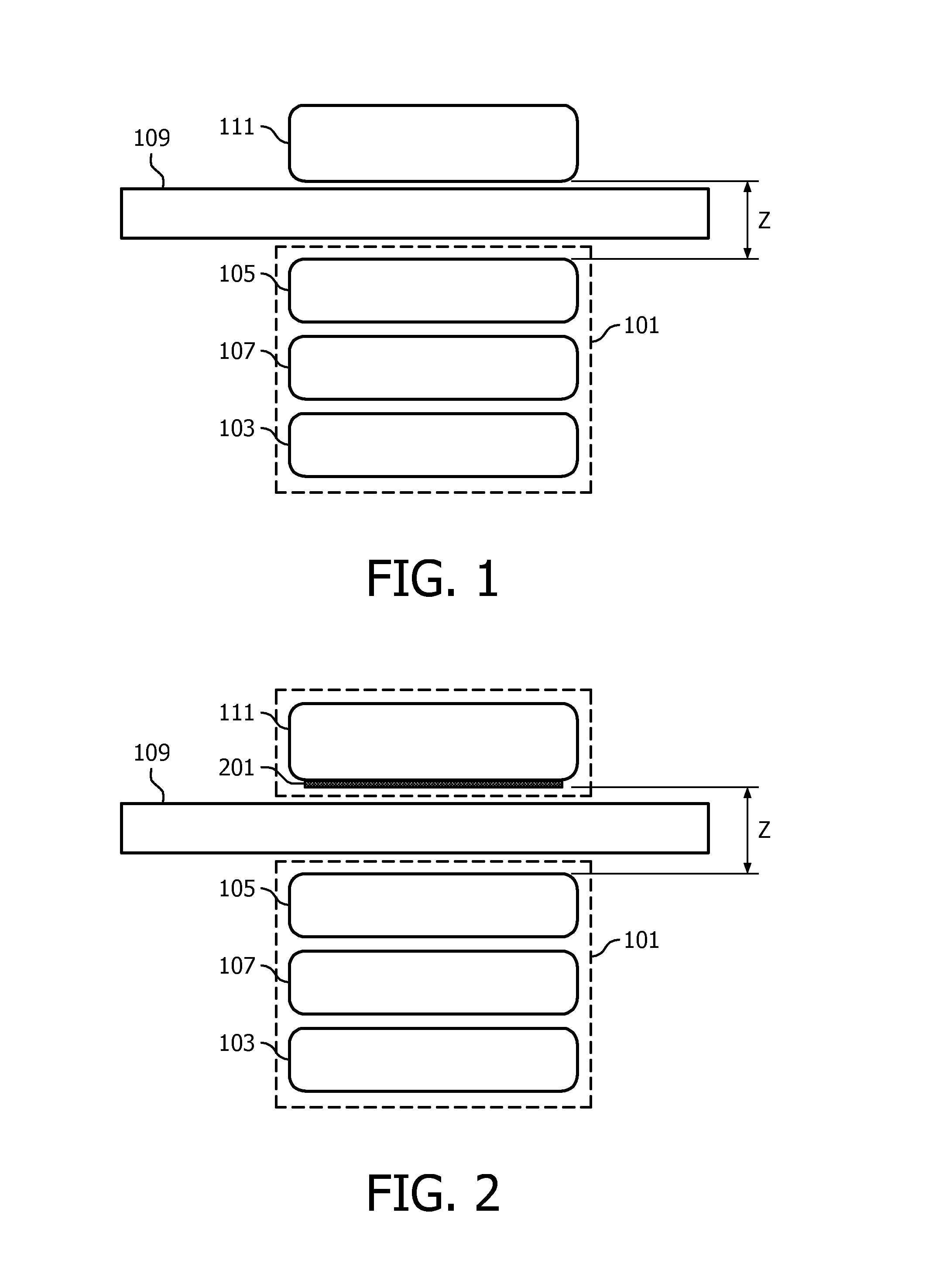
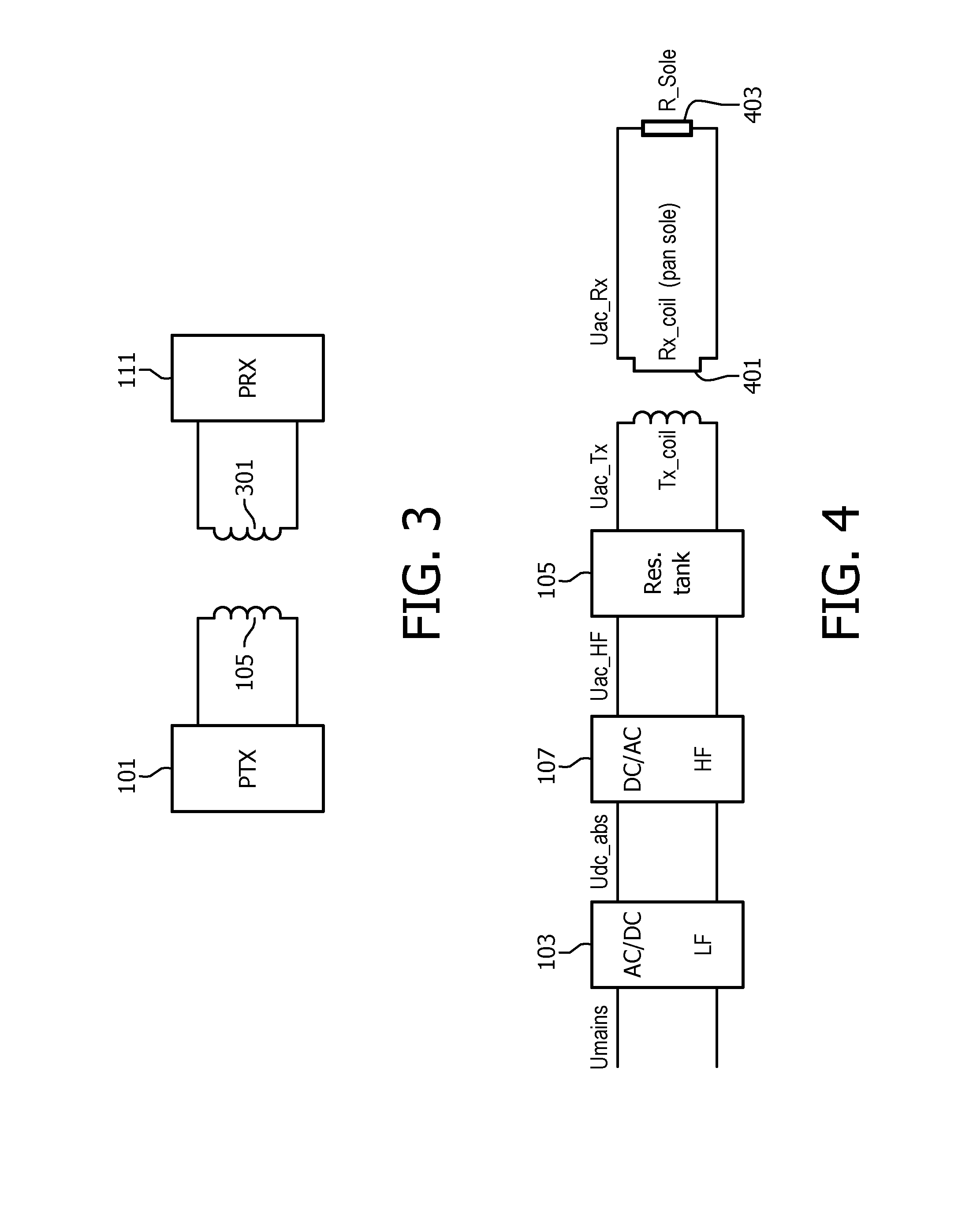
[0120]FIG. 3 illustrates an example of a power transfer system in accordance with some embodiments of the invention. The power transfer system comprises a power transmitter 101 which includes (or is coupled to) a transmitter coil / inductor 105. The system further comprises a power receiver 111 which includes (or is coupled to) a receiver coil / inductor 101. The receiver coil / inductor may in some embodiments be a conductive element such as specifically a heating element, i.e. it may be anything in which an electrical signal is induced when exposed to a varying magnetic field.

[0121]The system provides a wire...


PUM


Abstract

A thermal barrier for a wireless power transfer system comprises a first surface area (807) for coupling to a power receiver (111) to be powered by a first electromagnetic signal and a second surface area (805) for coupling to a power transmitter (101) providing a second electromagnetic signal. The thermal barrier (801) further comprises a power repeater (803) with a resonance circuit including an inductor and a capacitor. The power repeater (803) is arranged to generate the first electromagnetic signal by concentrating energy of the second electromagnetic signal towards the first surface area (807). The thermal barrier may provide thermal protection of the power transmitter (101) without unacceptable impact on the power transfer operation.

Description

FIELD OF THE INVENTION[0001]The invention relates to wireless power transfer and in particular, but not exclusively, to wireless power transfer for heating appliances.BACKGROUND OF THE INVENTION[0002]Many systems require a wiring and / or electrical contacts in order to supply electrical power to devices. Omitting these wires and contacts provides for an improved user experience. Traditionally, this has been achieved using batteries located in the devices but this approach has a number of disadvantages including extra weight, bulk and the need to frequently replace or recharge the batteries. Recently, the approach of using wireless inductive power transfer has received increasing interest.[0003]Part of this increased interest is due to the number and variety of portable and mobile devices having exploded in the last decade. For example, the use of mobile phones, tablets, media players etc. has become ubiquitous. Such devices are generally powered by internal batteries and the typical ...

Claims


Application Information

Patent Timeline
Patent Type & Authority Applications(United States)
IPC IPC(8): H02J50/12H05B6/12H05B6/06
CPCH02J50/12H05B2213/07H05B6/1236H05B6/062H02J50/10H02J50/00Y02B40/00H02J5/005
Inventor VAN WAGENINGEN, ANDRIESETTES, WILHELMUS GERARDUS MARIASTARING, ANTONIUS ADRIAAN MARIAKABLAU, JOHANNES GERARDUS FREDERICUS
Owner KONINKLJIJKE PHILIPS NV
Why Eureka
Try Eureka