
Body diode conduction optimization in mosfet synchronous rectifier

a synchronous rectifier and diode technology, applied in the direction of electric variable regulation, process and machine control, instruments, etc., can solve the problems of inefficient sr turn off in continuous conduction mode, inability to allow sr switch in fast transients, and high cost of solutions. achieve the effect of efficient turn off operation

Active Publication Date: 2016-10-06
JOULWATT TECH INC LTD
View PDF5 Cites 48 Cited by
  • Summary
  • Abstract
  • Description
  • Claims
  • Application Information

AI Technical Summary

Benefits of technology

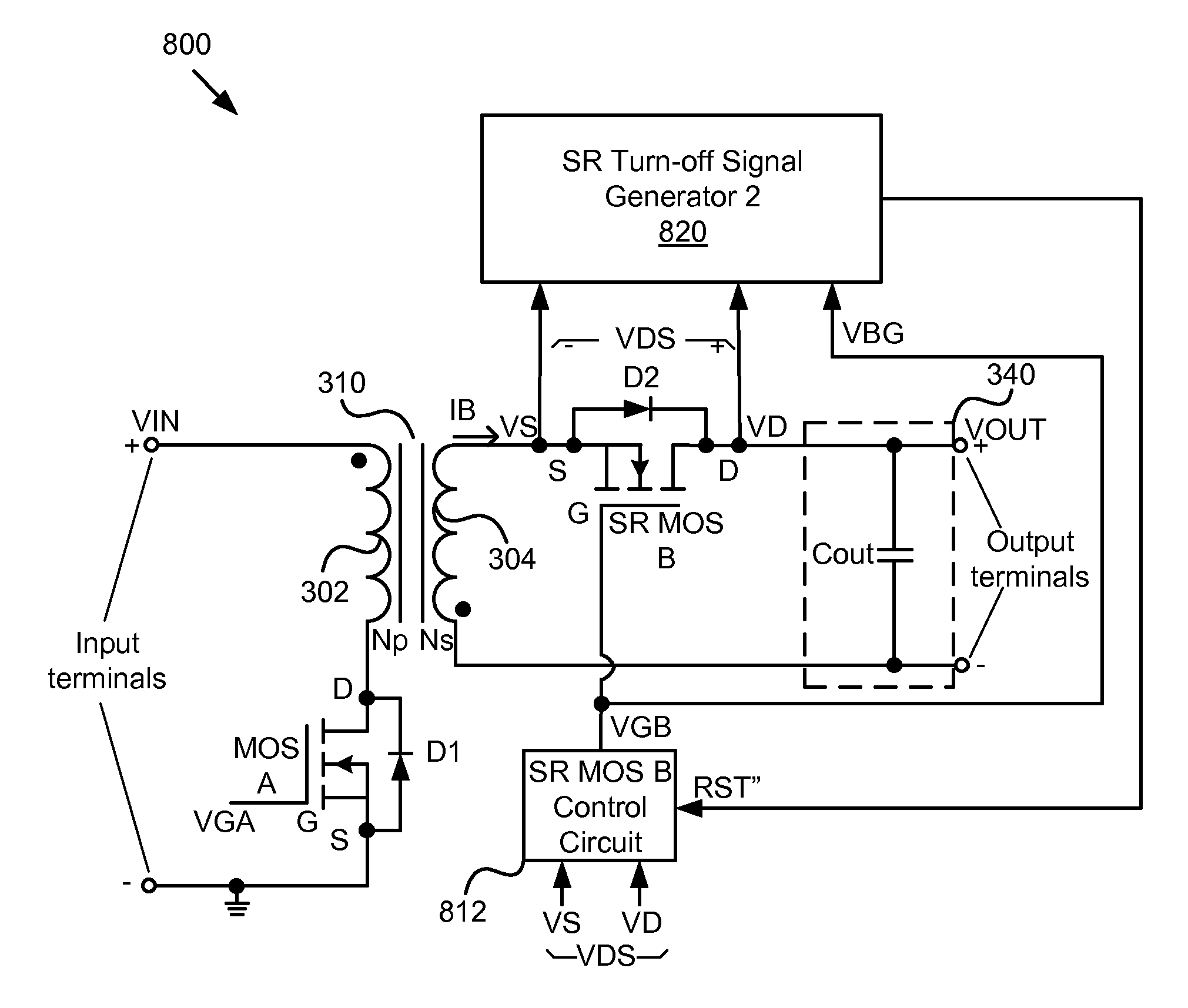
The patent describes an apparatus for efficiently turning off an SR MOSFET switch in a self-synchronized DC-DC converter with synchronous rectification. The apparatus includes a logic unit with multiple modules to execute the necessary steps. These modules include an SR turn-off signal generator to terminate conduction of theSR MOSFET at an appropriate time to minimize its conduction time. A self-synchronized control circuit responsive to the turn-off signal turns off the SR MOSFET. The technical effect of this patent is that it provides a more efficient way to turn off an SR MOSFET switch in a DC-DC converter, which can save power and improve efficiency.

Problems solved by technology

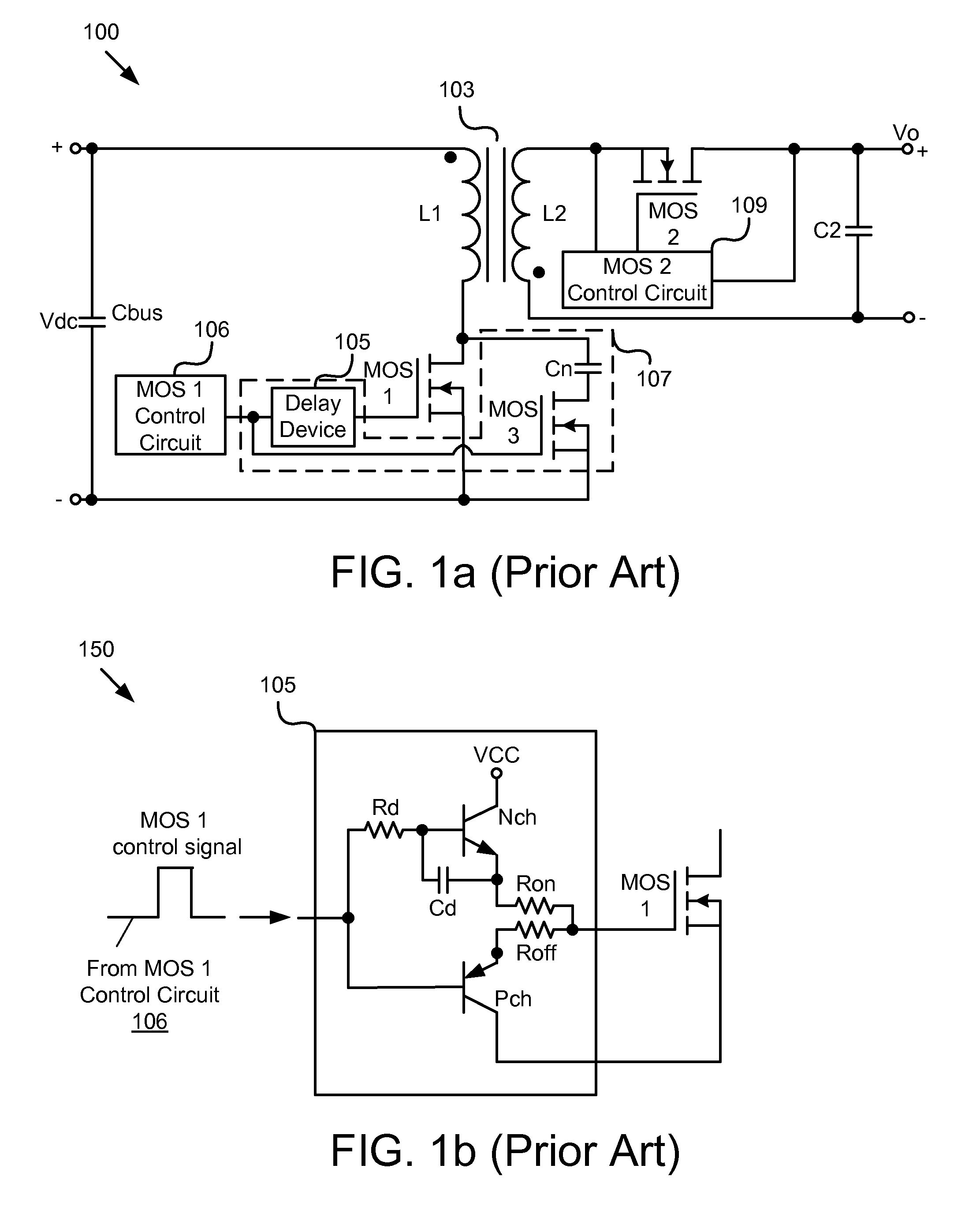
Although conventional self-synchronized flyback DC-DC converters with synchronous rectification operate quite well in a discontinuous conduction mode (“DCM”), they experience an inefficient SR turn off in a continuous conduction mode (“CCM”).
Up to now solutions to that problem are somewhat costly.
The fast transients do not allow the SR switch MOS 2 on the secondary side to turn off quickly enough.
This results in rather significant and undesirable reverse currents flowing through MOS 2.
Nevertheless, this delay generator 107 utilizing a number of discrete components on the primary side is not cost effective.

Method used


Image

  • Body diode conduction optimization in mosfet synchronous rectifier
  • Body diode conduction optimization in mosfet synchronous rectifier
  • Body diode conduction optimization in mosfet synchronous rectifier

Examples


Embodiment Construction

[0027]Reference throughout this specification to “one embodiment,”“an embodiment,” or similar language means that a particular feature, structure, or characteristic described in connection with the embodiment is included in at least one embodiment. Thus, appearances of the phrases “in one embodiment,”“in an embodiment,” and similar language throughout this specification may, but do not necessarily, all refer to the same embodiment, but mean “one or more but not all embodiments” unless expressly specified otherwise. The terms “including,”“comprising,”“having,” and variations thereof mean “including but not limited to” unless expressly specified otherwise. An enumerated listing of items does not imply that any or all of the items are mutually exclusive and / or mutually inclusive, unless expressly specified otherwise. The terms “a,”“an,” and “the” also refer to “one or more” unless expressly specified otherwise.

[0028]Furthermore, the described features, advantages, and characteristics o...


PUM


Abstract

To maximize power efficiency, dead time between “on” times of a synchronous rectifier (“SR”) MOSFET switch and a main switch for CCM operation in particular in isolated and non-isolated self-driven synchronous DC-DC converters needs to be optimized. To accomplish that objective, the latest conduction time t of a body diode of the SR MOSFET following conduction thereof is determined, compared with a selected fixed optimum period T1, and incrementally or decrementally adjusted in a subsequent switching cycle while t is unequal to T1, depending on whether t is shorter or longer than T1, so that t eventually is made substantially equal to T1 in length. This process is to be repeated continuously.

Description

BACKGROUND[0001]1. Field[0002]The subject matter disclosed herein relates to a switching power supply converter and more particularly relates to efficient operation of a DC-DC converter using a synchronous rectifier (“SR”) MOSFET.[0003]2. Description of the Related Art[0004]Although conventional self-synchronized flyback DC-DC converters with synchronous rectification operate quite well in a discontinuous conduction mode (“DCM”), they experience an inefficient SR turn off in a continuous conduction mode (“CCM”). Up to now solutions to that problem are somewhat costly. For example, FIG. 1a is a block diagram of a conventional self-synchronized flyback DC-DC converter with synchronous rectification, using a delay generator 107 on the primary side to avoid adverse effects of fast transients resulting from a hard switching to “on” of the primary power switch MOS 1. The fast transients do not allow the SR switch MOS 2 on the secondary side to turn off quickly enough. This results in rath...

Claims


Application Information

Patent Timeline
Patent Type & Authority Applications(United States)
IPC IPC(8): H02M3/335H02M1/42
CPCH02M1/42H02M3/33592H02M1/38H02M3/1588H02M1/0009H02M1/0058Y02B70/10
Inventor WONG, PITLEONGREN, YUANCHENGZHOU, XUNWEI
Owner JOULWATT TECH INC LTD
Learn More