Elastic wave device and filter device

a filter device and wave technology, applied in the direction of piezoelectric/electrostrictive devices, device material selection, piezoelectric/electrostrictive devices, etc., can solve the problems of large insertion loss, too large, transverse-mode ripple frequency characteristics, etc., to achieve favorable resonance characteristics or filter characteristics, the effect of effectively reducing transverse-mode ripples

Active Publication Date: 2016-10-06
MURATA MFG CO LTD
View PDF11 Cites 27 Cited by
  • Summary
  • Abstract
  • Description
  • Claims
  • Application Information

AI Technical Summary

Benefits of technology

[0032]According to various preferred embodiments of the present invention, the transverse-mode ripples are effectively reduced. Therefore, an elastic wave device having favorable resonance characteristics or filter characteristics is provided.

Problems solved by technology

The elastic wave device described in WO12 / 086639 has a problem that the frequency characteristic thereof has transverse-mode ripples.
However, in the elastic wave device in which an elastic wave is confined by using a high acoustic velocity film as described in WO12 / 086639, when the upper and lower busbars extend obliquely with respect to the surface-acoustic-wave propagation direction at the same angle as described in Japanese Unexamined Patent Application Publication No. 2000-286663, the oblique angle is 18° or more and 72° or less, and is too large.
Therefore, a large insertion loss occurs.

Method used


Image

  • Elastic wave device and filter device
  • Elastic wave device and filter device
  • Elastic wave device and filter device

Examples


example 3

, and

[0078]FIG. 45 is a plan view illustrating the main portion of an electrode structure of an elastic wave device according to an eighth preferred embodiment of the present invention.

[0079]FIG. 46 shows the return loss characteristics of Example 2, Example 3, and Example 4.

[0080]FIG. 47 is a plan view illustrating the main portion of an electrode structure of an elastic wave device according to a ninth preferred embodiment.

[0081]FIG. 48 shows the return loss characteristics of Example 2, Example 3, and Example 5.

[0082]FIG. 49 is a plan view illustrating the main portion of an electrode structure of an elastic wave device according to a tenth preferred embodiment of the present invention.

[0083]FIG. 50 shows the return loss characteristics of Example 2, Example 3, and Example 6.

[0084]FIG. 51 shows changes in the return loss characteristic in the case where a dimension TH of projecting portions is changed.

[0085]FIG. 52 shows changes in the return loss characteristic in the case where...

seventh preferred embodiment

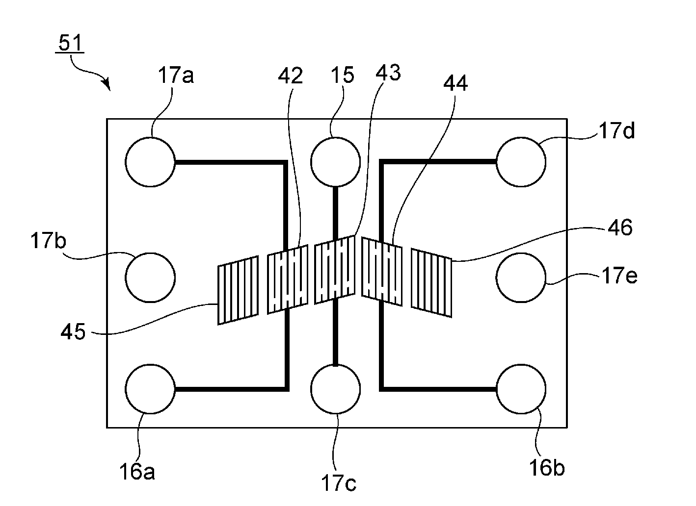
[0230]FIG. 43 is a partial plan view illustrating the main portion of an IDT electrode of an elastic wave device according to a seventh preferred embodiment of the present invention. The elastic wave device according to the present preferred embodiment is similar to the elastic wave device 1 according to the first preferred embodiment except that projecting portions 121 and 122 illustrated in FIG. 43 are provided. Therefore, the projecting portions 121 and 122 will be described with regard to other components the description of the first preferred embodiment is to be referred to.

[0231]FIG. 43 illustrates a region in which a distal end 11c1 of a first electrode finger 11c and a distal end 11e1 of a first dummy electrode finger 11e face each other with a gap therebetween. Second electrode fingers 11d and 11d are present on the sides of the gap.

[0232]The shape of the projecting portions 121 is not particularly limited. In the present preferred embodiment, the projecting portions 121 pr...


PUM


Abstract

An elastic wave device includes IDT electrodes stacked on a piezoelectric thin film. The IDT electrode includes a plurality of first electrode fingers and a plurality of second electrode fingers. A line connecting the distal ends of the first electrode fingers or the distal ends of the second electrode fingers extends obliquely with respect to a propagation direction of an elastic wave at an oblique angle ν. The oblique angle ν is about 0.4° or more and about 10° or less.

Description

CROSS REFERENCE TO RELATED APPLICATIONS[0001]This application claims the benefit of priority to Japanese Patent Application 2013-269249 filed Dec. 26, 2013 and is a Continuation Application of PCT / JP2014 / 083725 filed on Dec. 19, 2014. The entire content of each application are hereby incorporated by reference.BACKGROUND OF THE INVENTION[0002]1. Field of the Invention[0003]The present invention relates to an elastic wave device for use in a resonator, a band pass filter, or the like. More particularly, the present invention relates to an elastic wave device including a piezoelectric thin film made of LiTaO3 and a filter device including the elastic wave device.[0004]2. Description of the Related Art[0005]WO12 / 086639 discloses an elastic wave device in which a high acoustic velocity film, a low acoustic velocity film, a LiTaO3 film, and an IDT electrode are stacked on a support substrate in that order. According to WO12 / 086639, a leaky wave that propagates through the LiTaO3 film is u...

Claims


Application Information

Patent Timeline
Patent Type & Authority Applications(United States)
IPC IPC(8): H03H9/64H03H9/02H01L41/08H01L41/047H01L41/18
CPCH03H9/6496H01L41/047H03H9/02574H01L41/081H01L41/0477H01L41/18H03H9/14532H03H9/14576H03H9/14579H03H9/14594H10N30/85H10N30/87H10N30/877H10N30/10513
Inventor YAMANE, TAKASHIIWAMOTO, HIDEKIOKADA, KEIJIKIDO, SYUNSUKEOTAGAWA, MASANORIHATSUDA, IPPEIITO, KOREKIYO
Owner MURATA MFG CO LTD
Why Eureka
Try Eureka