System for monitoring and controlling air quality during welding

a technology for monitoring and controlling air quality, applied in shielding gas supply/evacuation devices, manufacturing tools, instruments, etc., can solve the problems of less practicability of local exhaust ventilation in large welding areas and general ventilation not always protecting the immediate breathing zone of welders

Inactive Publication Date: 2016-10-13
LINCOLN GLOBAL INC
View PDF8 Cites 16 Cited by
  • Summary
  • Abstract
  • Description
  • Claims
  • Application Information

AI Technical Summary

Benefits of technology

[0006]In accordance with one aspect of the present invention, provided is a fume reduction system. The fume reduction system includes an electric arc torch. A consumable wire electrode is operatively connected to the electric arc torch and receives electrical energy from the electric arc torch. The consumable wire electrode establishes an electrical arc between the consumable wire electrode and a workpiece. An air quality sensor monitors the air quality near the electric arc torch and generates an air quality signal corresponding to the air quality. A power supply is operatively connected to the electric arc torch and to the air quality sensor. The power supply is configured to supply electrical energy for generating an electrical arc at the electric arc torch. The power supply controls the wire feed speed of the consumable wire electrode by receiving the air quality signal and automatically changing the wire feed speed from a first positive speed to a second positive speed based on the level of the air quality signal.
[0007]In accordance with another aspect of the present invention, provided is a fume reduction system. The fume reduction system includes an electric arc torch. A consumable wire electrode is operatively connected to the electric arc torch and receives electrical energy from the electric arc torch. The consumable wire electrode establishes an electrical arc between the consumable wire electrode and a workpiece. An air quality sensor monitors the air quality near the electric arc torch and generates an air quality signal corresponding to the air quality. A power supply is operativ...

Problems solved by technology

For example, general ventilation does not always protect the welder's immediate ...

Method used


Image

  • System for monitoring and controlling air quality during welding
  • System for monitoring and controlling air quality during welding
  • System for monitoring and controlling air quality during welding

Examples


Embodiment Construction

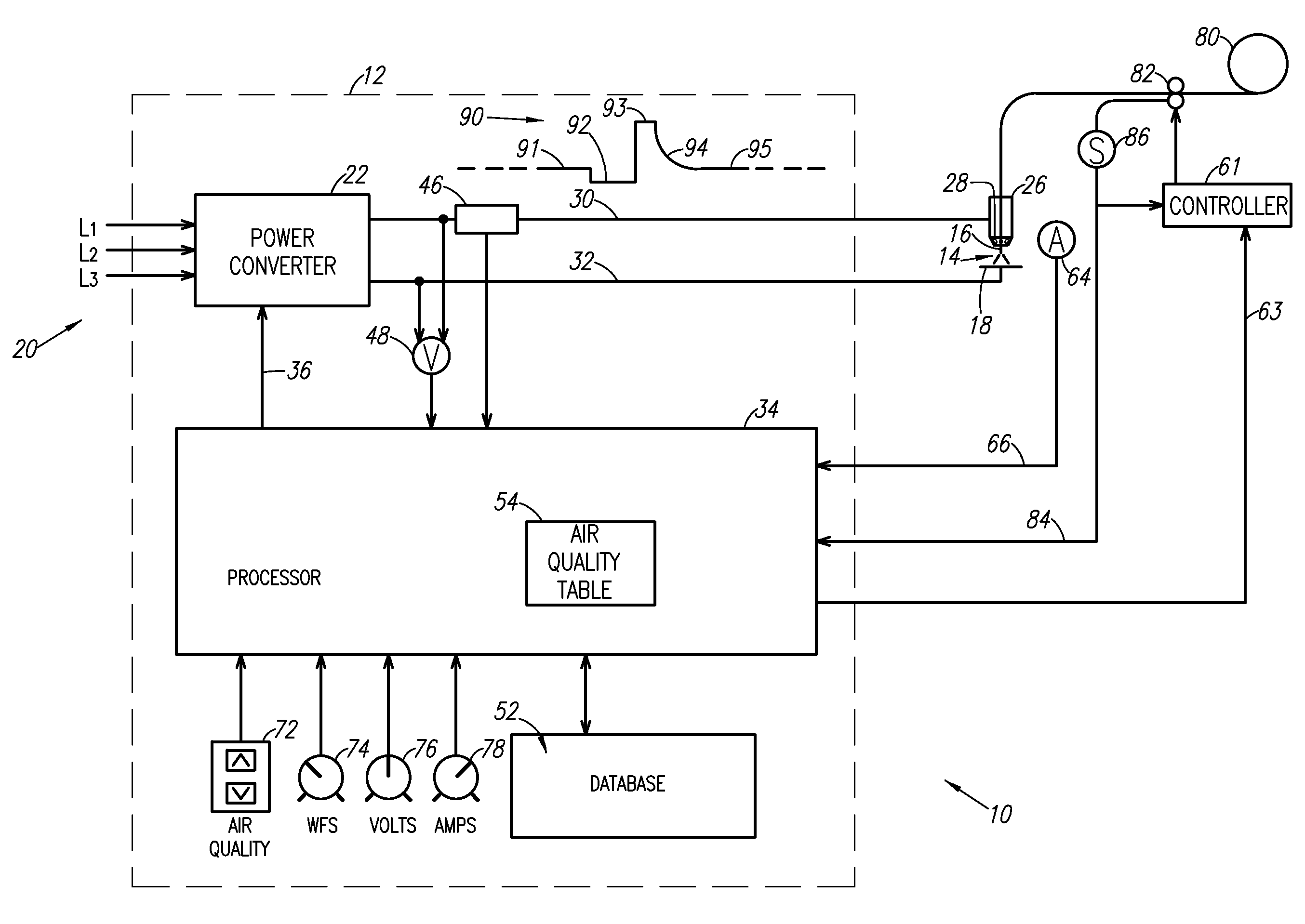
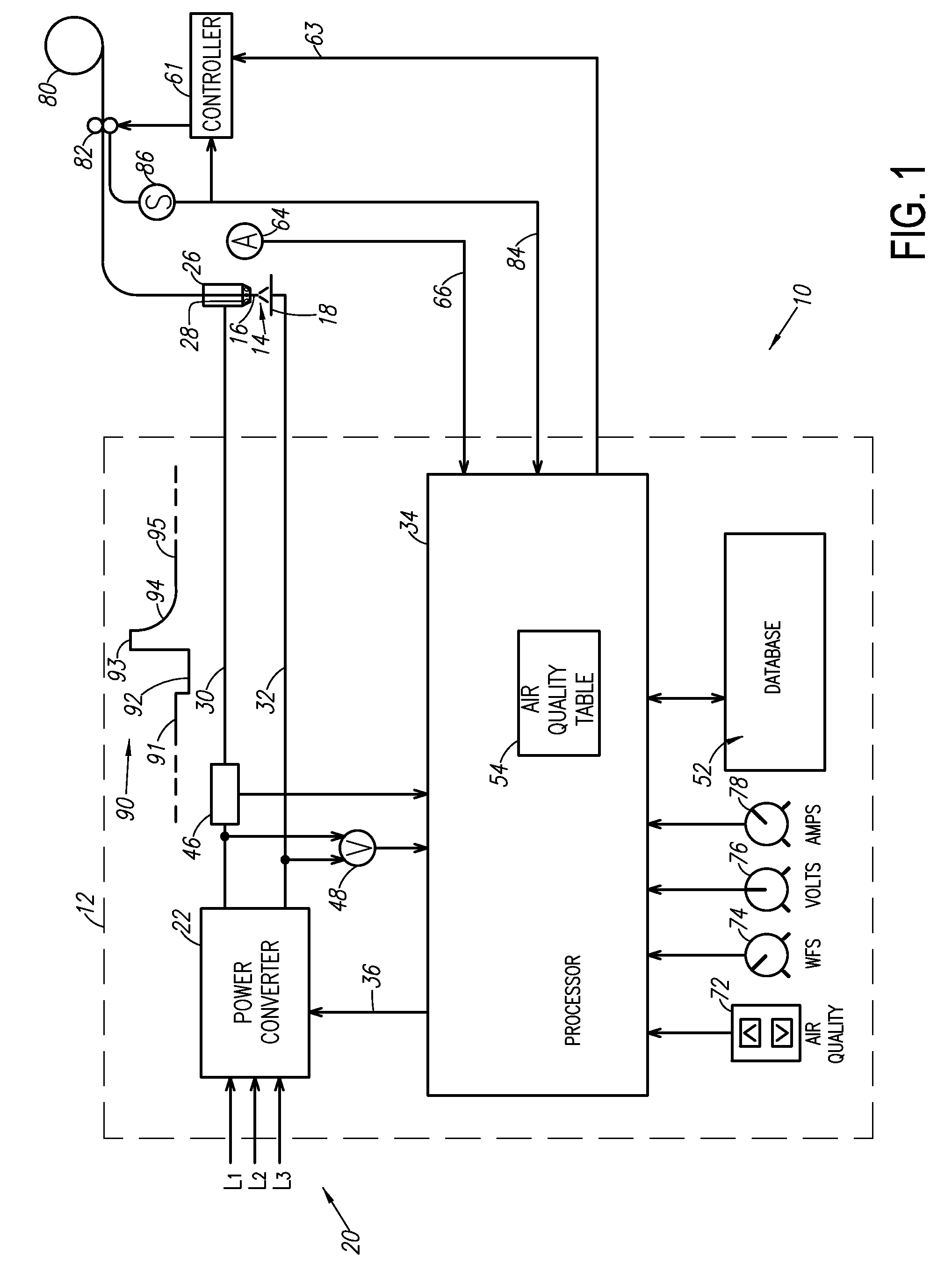
[0017]The present invention relates to monitoring and controlling the air quality near the welding operator in arc welding systems. The present invention will now be described with reference to the drawings, wherein like reference numerals are used to refer to like elements throughout. It is to be appreciated that the various drawings are not necessarily drawn to scale from one figure to another nor inside a given figure, and in particular that the size of the components are arbitrarily drawn for facilitating the understanding of the drawings. In the following description, for purposes of explanation, numerous specific details are set forth in order to provide a thorough understanding of the present invention. It may be evident, however, that the present invention can be practiced without these specific details. Additionally, other embodiments of the invention are possible and the invention is capable of being practiced and carried out in ways other than as described. The terminolog...


PUM

PropertyMeasurementUnit
Speedaaaaaaaaaa
Shapeaaaaaaaaaa
Flammabilityaaaaaaaaaa

Abstract

A fume reduction system includes an electric arc torch, a consumable wire electrode, an air quality sensor, and a power supply operatively connected to the electric arc torch and the air quality sensor. The air quality sensor monitors air quality near the electric arc torch and generates an air quality signal corresponding to the air quality. The power supply supplies electrical energy for generating the electrical arc and controls the wire feed speed of the consumable wire electrode. The power supply further receives the air quality signal and automatically reduces the wire feed speed from a first positive speed to a second positive speed based on the level of the air quality signal.

Description

BACKGROUND OF THE INVENTION[0001]1. Field of the Invention[0002]The present invention relates to arc welding systems, and in particular to a system for monitoring and controlling the air quality near a welding operator during arc welding.[0003]2. Description of Related Art[0004]Significant quantities of fumes, gases, vapors, dusts or the like (all of which are referred to herein as “fumes” or “welding fumes”) are typically produced as by-products of most welding processes. These fumes are created at various locations, such as around the welding gun when working proximate a workpiece or in the immediate vicinity of the welding operator. Some industrial regulations may require that the fumes be monitored and extracted from the work area with minimal or no adverse health effects to the welding operators. The health hazard potential related to welding fumes depends on the concentration and toxicity of the materials involved (types of metals, fluxes, gases, coatings, etc.), the length of...

Claims


Application Information

Patent Timeline
IPC IPC(8): B23K9/095B23K9/32G06F17/30B23K9/12
CPCB23K9/0953B23K9/0956G06F17/30392B23K9/321B23K9/125A61F9/068B23K9/173B23K9/325Y02D10/00
Inventor ENYEDY, EDWARD A.
Owner LINCOLN GLOBAL INC
Why Eureka
Try Eureka