Method for grinding spring with high quality and high efficiency

a technology of high efficiency and grinding method, which is applied in the direction of grinding heads, grinding drives, manufacturing tools, etc., can solve the problems of serious affecting the vertical low production efficiency, and low precision of spring grinding, and achieve high verticality precision of grinding, high production efficiency, and high production efficiency

Active Publication Date: 2016-10-13
SHAOXING JIADU SPRING MACHINE
View PDF0 Cites 2 Cited by
  • Summary
  • Abstract
  • Description
  • Claims
  • Application Information

AI Technical Summary

Benefits of technology

[0022]First, high production efficiency, which is resulted from: firstly, the complete spring is ground in the plane of the grinding wheels simultaneously; and secondly, at least one of the grinding wheels is configured to comprise an inner grinding wheel and an outer grinding wheel which are rotated in opposite directions, such that the spring can be ground in a revolving state. Thus, a great feeding amount of grinding can be performed. As a result, the production efficiency will be about twice that of the current numerical control spring grinder.
[0023]Second, high verticality precision of grinding and high stability, which is resulted from: 1, The spring is moved back and forth in the plane of the grinding wheels from the inner diameters to the outer diameters of the grinding wheels, so every point on the grinding wheels is involved in grinding each spring and subjected to equal amount of grinding, such that the grinding wheels are worn uniformly, improving the precision of grinding and stability. 2, At least one of the grinding wheels is configured to comprise an inner grinding wheel and an outer grinding wheel, such that the spring can be ground in a revolving state.
[0024]Finally, because the present mechanism includes a mechanism having the combination of the two technical features described above, new technical features are farmed by combining the two technical features. The new technical features enable every point on the end faces of the spring to be ...

Problems solved by technology

First, angle β is generally of 60 to 70 degrees, so that when the upper grinding wheel is moved downwardly, the time taken for the spring at point a on the grinding disc to pass through point b from point a to reach to point cis only about 17% of the time taken for the grinding disc to rotate in a full circle. Therefore, this results in three consequences: 1), Only about 17% of the complete spring is ground in the plane of the grinding wheels simultaneously, which leads to a low production efficiency.
2), The amount of grinding of each spring is only 17% of the amount of downward moving of the upper grinding wheel when the grinding disc is rotated in a full circle, while for the remaining 83% of the amount of moving, the spring is actually external to the grinding wheel and is not ground, which is unreasonable. The consequence of this is that the grinding at point a of the grinding wheel is very fast due to the sudden increase of the amount of grinding at point a, while the grinding at point b is slow and point c is almost not ground. Thus, the end face of the grinding wheel finally takes the shape of a truncated cone as shown in FIG. 3, which seriously affect the vertical precision of the spring grinding.
3), when the two grinding wheels are grinding, only the position coincident with t...

Method used


Image

  • Method for grinding spring with high quality and high efficiency
  • Method for grinding spring with high quality and high efficiency
  • Method for grinding spring with high quality and high efficiency

Examples


Embodiment Construction

[0037]The present invention is further illustrated below in connection with the accompanying drawings and specific embodiments.

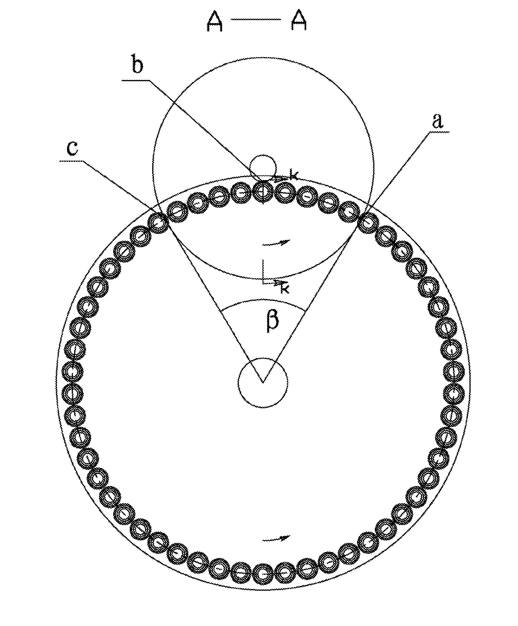
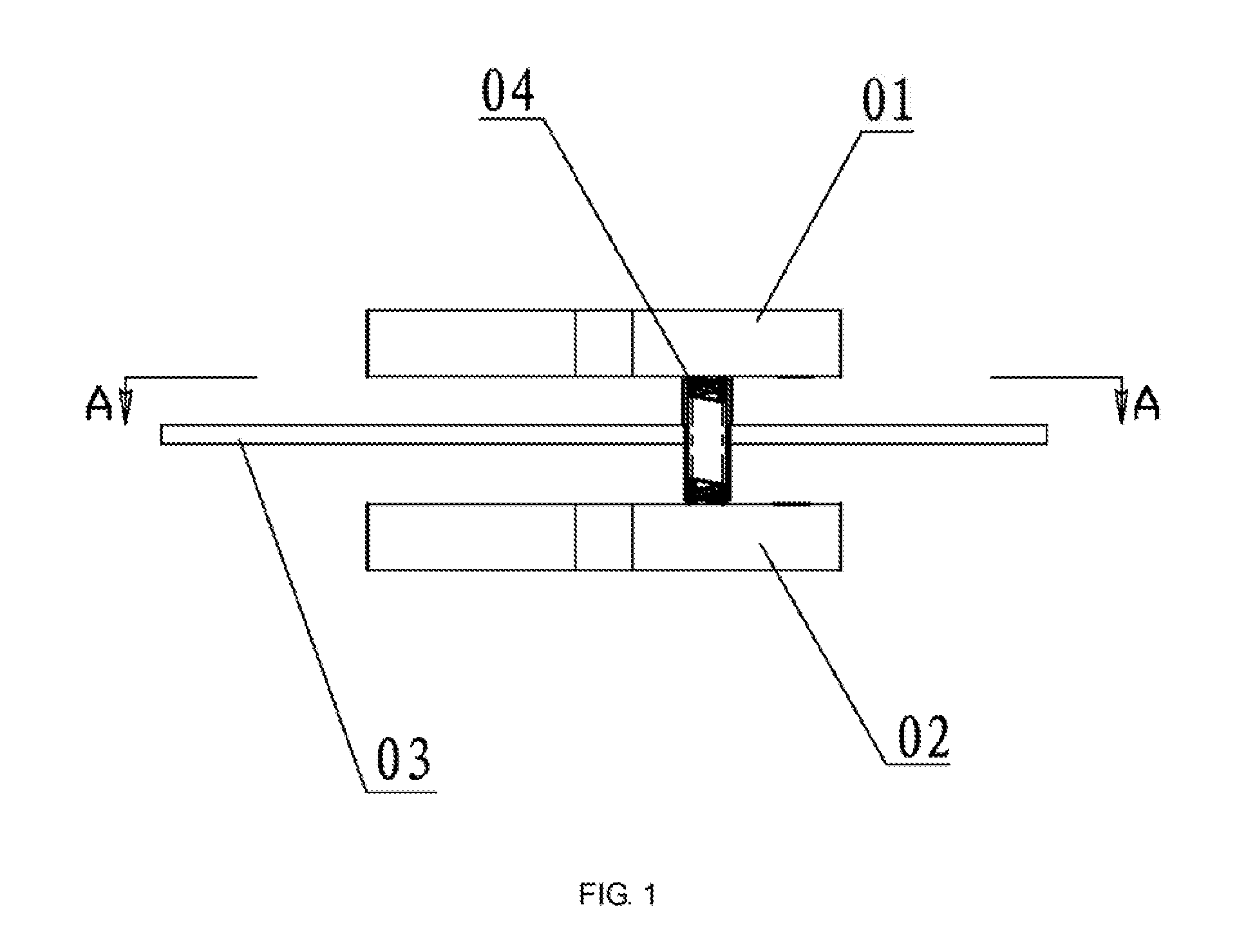
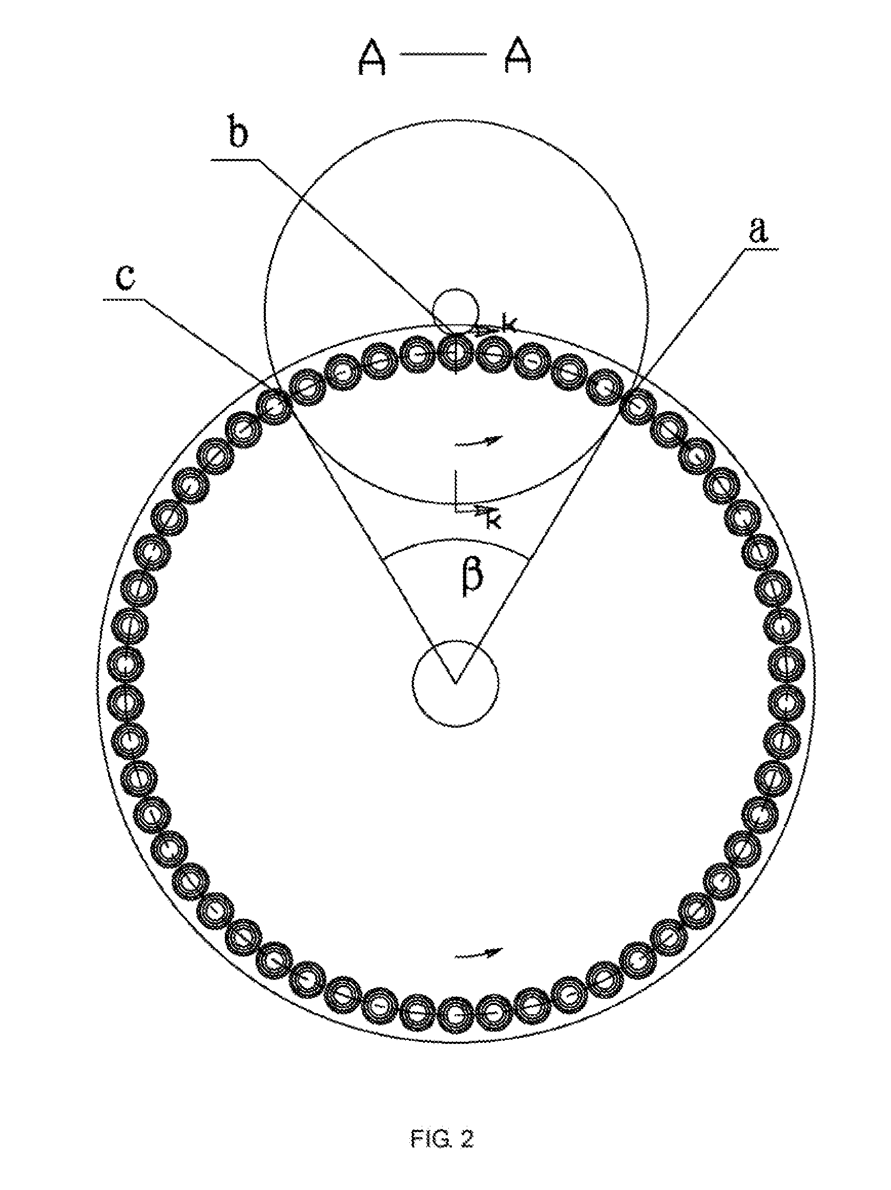
[0038]As shown in the figures, a method and mechanism for grinding a spring is disclosed in the present invention. The mechanism comprises an upper grinding wheel 1 and a lower grinding wheel 2, and at least one of said upper grinding wheel and said lower grinding wheel 2 comprises an inner grinding wheel 21 and an outer grinding wheel 24. In the present embodiment, the upper grinding wheel 1 is selected to have an integral structure, while the lower grinding wheel 2 comprises the inner grinding wheel 21 and the outer grinding wheel 24, wherein the dimension of the outer diameter of the inner grinding wheel 21 is slightly less than the dimension of the inner diameter of the outer grinding wheel 24, and the inner grinding wheel 21 is fitted in the outer grinding wheel 24. The inner grinding wheel 21 and the outer grinding wheel 24 are rotated in opposite dire...


PUM


Abstract

Disclosed is a method for grinding a spring with high quality and high efficiency, comprising the steps as follows: firstly, at least one of an upper grinding wheel (1) and a lower grinding wheel (2) is configured to comprise an inner grinding wheel (21) and an outer grinding wheel (24), wherein the inner grinding wheel (21) is fitted in the outer grinding wheel (24); the inner grinding wheel (21) or the outer grinding wheel (24) is driven by a transmission mechanism, the inner grinding wheel (21) and the outer grinding wheel (24) rotating in opposite directions; after a complete spring is fed to a space between the upper grinding wheel (1) and the lower grinding wheel (2), the complete spring is moved back and forth in the plane of the grinding wheels; and then the upper grinding wheel (1) is moved downwardly such that two end faces of the spring are ground by the grinding wheels, and when the height of the ground spring meets the requirement, the upper grinding wheel (1) is stopped moving downwardly and is returned to the original point later. Then, the ground spring movement is stopped and it is moved away from the space between the two grinding wheels, i.e., the complete spring is removed. In this way, the spring is ground in a revolving state, which can improve the yield and quality of ground springs, save energy and protect the environment, and result in a low cost of grinding, a simple structure, low cost for manufacturing parts, long persistence in precision of mechanisms, and good stability.

Description

CROSS-REFERENCE TO RELATED APPLICATIONS[0001]This application is a continuation of International Patent Application No. PCT / CN2014 / 078069 with a filing date of May 22, 2014, designating the United States, now pending, and further claims priority to Chinese Patent Application No. 201310753809.7 with a filing date of Dec. 31, 2013, No. 201310753820.3 with a filing date of Dec. 31, 2013 and No. 201320892681.8 with a filing data of Dec. 31, 2013. The content of the aforementioned applications, including any intervening amendments thereto, are incorporated herein by reference.TECHNICAL FIELD[0002]The present invention relates to the field of spring grinding, and in particular to a method for grinding a spring with high quality and, high efficiency.BACKGROUND OF THE PRESENT INVENTION[0003]Currently, the basic mechanisms of numerical control dual-end face spring grinders comprise an upper grinding wheel 01 and a lower grinding wheel 02, as shown in schematic views in FIGS. 1 and 2. The upp...

Claims


Application Information

Patent Timeline
IPC IPC(8): B24B7/16B24B47/00B24B41/047B24B41/06B24B7/17B24B41/04
CPCB24B7/167B24B7/17B24B7/162B24B47/00B24B41/047B24B41/067B24B41/04B24B47/04B24B37/28
Inventor YU, JIALINYU, DUHUANG, HUALI
Owner SHAOXING JIADU SPRING MACHINE
Why Eureka
Try Eureka