System and Method for Permanent Storage of Carbon Dioxide in Shale Reservoirs

a carbon dioxide and shale reservoir technology, applied in the direction of fluid removal, chemistry apparatus and processes, borehole/well accessories, etc., can solve the problems of increasing affecting the stability of the shale reservoir, so as to improve the risk of leakage

Inactive Publication Date: 2016-10-13
PROSTIM LABS
View PDF3 Cites 13 Cited by
  • Summary
  • Abstract
  • Description
  • Claims
  • Application Information

AI Technical Summary

Benefits of technology

[0051]Subject matter of this disclosure provides a method for sequestration in deep underground formations of large amounts of CO2, with improved risk of leakage such as, for example, long-term leakage.
[0056]Fracking is necessary to produce hydrocarbons from shale formations because shale has very low permeability (concrete is 102-104 times more permeable) and there has been little or no movement of fresh water (or waters of a different mineral content) since the rock was formed. Furthermore, shale is under-saturated to water and the level of salt in the connate water within the shale is often at salinity equal to the seawater the shale was deposited from. When shale is under-saturated, introducing fresh water or moderate salinity water in a frac, causes salts, some organics, and other minerals that were previously in equilibrium in the shale to becoming solubilized with the connate waters. It is important that the shale reservoir has been “isolated” from external chemistry for several million years. In other words, until the shale reservoir is fracked, there is no route for hydrocarbons to escape, meaning, for example, that if natural gas could be exchanged for CO2 and the reservoir returned to its pre-frack state the CO2 would be contained by the same forces that contained the gas for millions of years. Given that shale gas in the U.S. is formed during the Jurassic period, this gives a proven stability of over 100 million years.

Problems solved by technology

It has been stated that biological sequestration is a natural approach; however, despite this advantage it is known that significant disadvantages are associated with this approach.
Although the oceans represent possibly the largest potential CO2 sink, ocean sequestration involves problems including poorly understood physical and chemical processes, efficiency, cost, technical feasibility, and possibly the most worrying, long-term environmental impact.
In addition, ocean circulation poses legal, political and international limitations to this technology.
Carbon dioxide forms carbonic acid when dissolved in water, so ocean acidification is a significant consequence of elevated carbon dioxide levels, and limits the rate at which it can be absorbed into the ocean.
However, the total volume of material required to make an impact on global CO2 emissions would be cost prohibitive (Huijens, et al., 2005).
While in a typical well, the CO2 would be sealed by capping the well with cement, degradation of the cement may prevent such wells from being a long-term solution.
Carbonation rates were relatively low, but most detrimental were the cracking of specimens as a result of massive CaCO3 formation which comes along with expansion (Lesti et al., 2013).
Although some of the reactions with cement can be beneficial, a loss of compressive strength of the cement is observed (Condor and Asghan, 2009).
In summary, current CO2 geologic sequestration technology suffers various problems and inadequacies.
Failure of the geologic formation or reservoir to contain the CO2 due to cement failure may result in catastrophic release of vast quantities of CO2 at some undetermined point in the future.

Method used


Image

  • System and Method for Permanent Storage of Carbon Dioxide in Shale Reservoirs
  • System and Method for Permanent Storage of Carbon Dioxide in Shale Reservoirs
  • System and Method for Permanent Storage of Carbon Dioxide in Shale Reservoirs

Examples


Embodiment Construction

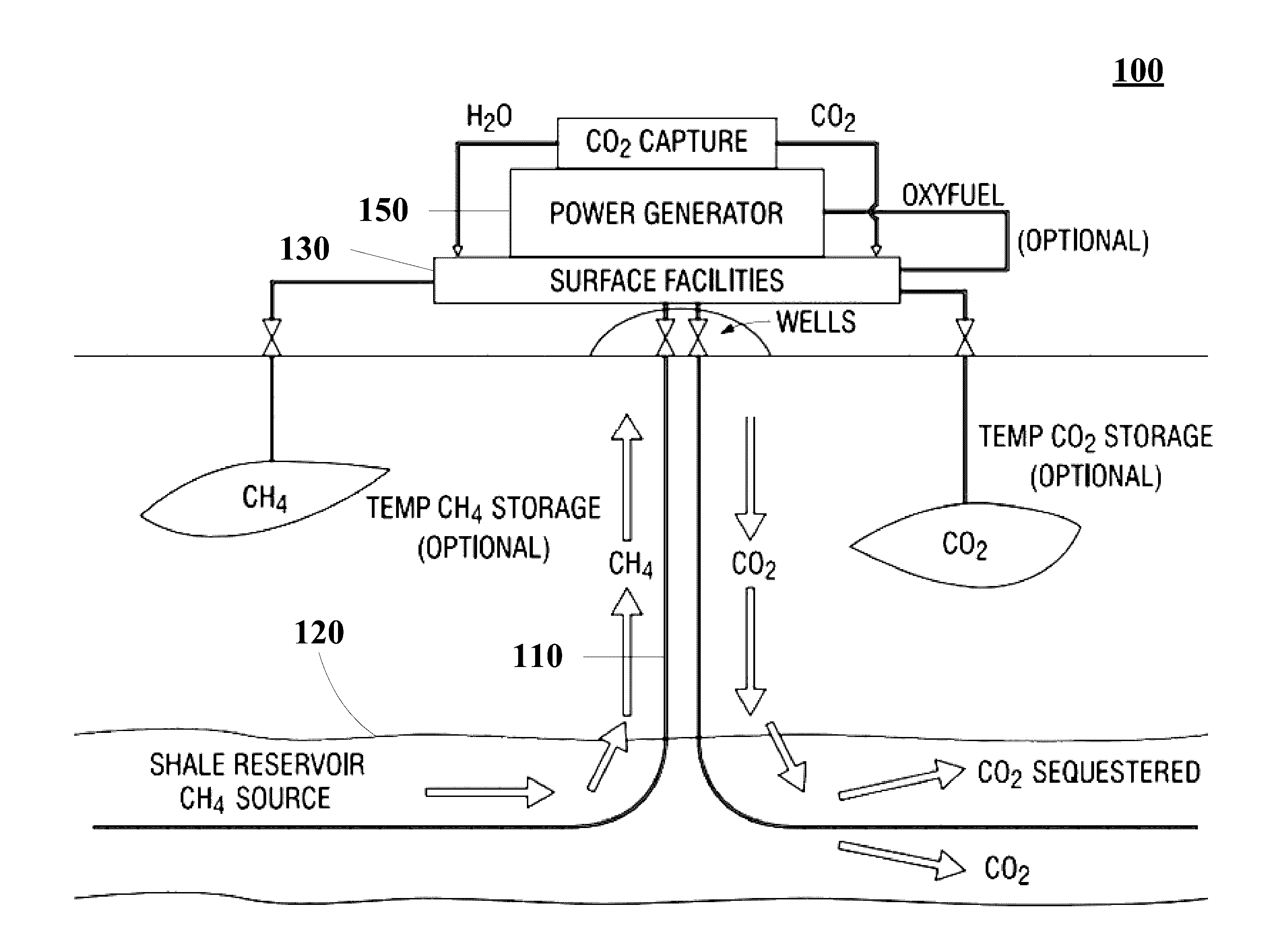
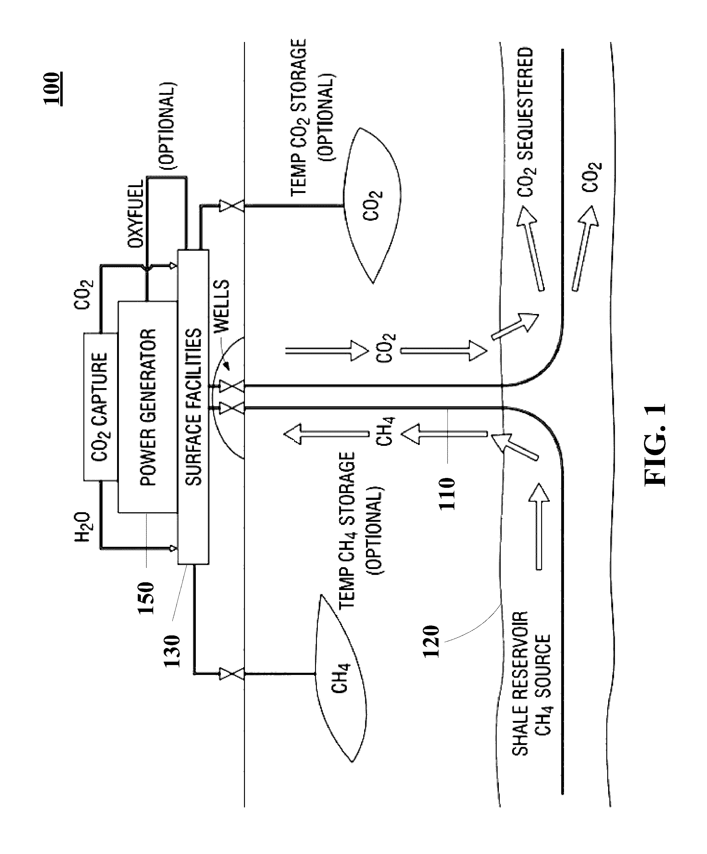
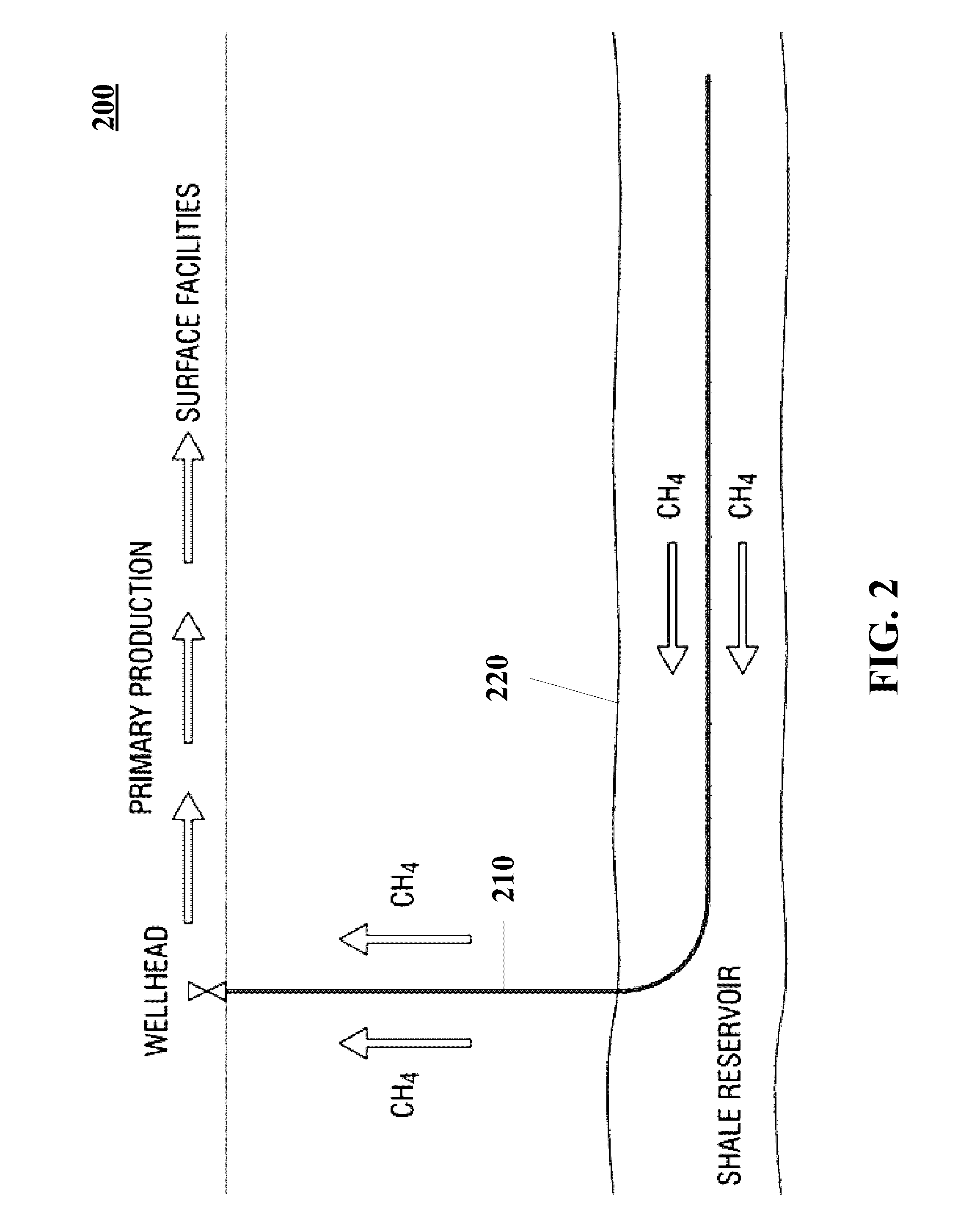
[0085]Reference now should be made to the drawings, in which the same reference numbers are used throughout the different figures to designate the same components.

[0086]Before describing selected embodiments of the present invention in detail, it is to be understood that the present invention is not limited to the particular embodiments described herein. The disclosure and description herein is illustrative and explanatory of one or more presently preferred embodiments of the invention and variations thereof, and it will be appreciated by those skilled in the art that various changes in the design, organization, order of operation, means of operation, equipment structures and location, methodology, and use of mechanical equivalents may be made without departing from the spirit of the invention.

[0087]As well, it should be understood the drawings are intended illustrate and plainly disclose presently preferred embodiments of the invention to one of skill in the art, but are not intend...


PUM


Abstract

Disclosed subject matter includes a system and method for the permanent storage of CO2 by removal of hydrocarbons such as natural gas and methane from a geologic formation, combustion to provide de-carbonized electricity, and introduction of carbon-containing compounds such as CO2 into the geologic formation.

Description

CROSS-REFERENCE TO RELATED APPLICATIONS[0001]This application is related to:[0002]U.S. Provisional Patent Application Ser. No. 62 / 010,302, filed Jun. 10, 2014;[0003]U.S. Provisional Patent Application Ser. No. 61 / 889,187, filed Oct. 10, 2013;[0004]U.S. Provisional Patent Application Ser. No. 62 / 036,284, filed Aug. 12, 2014;[0005]U.S. Provisional Patent Application Ser. No. 62 / 036,297, filed Aug. 12, 2014;[0006]U.S. Application for patent application Ser. No. 14 / 199,461, filed Mar. 6, 2014;[0007]U.S. Application for patent application Ser. No. 14 / 511,858, filed Oct. 10, 2014;[0008]U.S. Provisional Patent Application Ser. No. 61 / 774,237, filed Mar. 7, 2013;[0009]U.S. Provisional Patent Application Ser. No. 61 / 790,942, filed Mar. 15, 2013;[0010]U.S. Provisional Patent Application Ser. No. 61 / 807,699, filed Apr. 2, 2013;[0011]U.S. Provisional Patent Application Ser. No. 61 / 870,350, filed Aug. 27, 2013;[0012]U.S. Provisional Patent Application Ser. No. 61 / 915,093, filed Dec. 12, 2013;[00...

Claims


Application Information

Patent Timeline
Patent Type & Authority Applications(United States)
IPC IPC(8): E21B41/00E21B43/267E21B43/26
CPCE21B41/0064E21B43/267E21B43/26C09K8/60C09K8/62C09K8/80Y02C20/40
Inventor THRASH, JOHN F.
Owner PROSTIM LABS
Why Eureka
Try Eureka