Rotor damper

a damper and rotor technology, applied in the field of dampers, can solve the problems of resonance and flutter not being able to always avoid resonance, the blisk lacks inherent damping, and it is not possible to design a blisk that avoids resonance, etc., to achieve the effect of increasing energy dissipation, improving damping, and increasing frictional energy

Active Publication Date: 2016-10-13
ROLLS ROYCE PLC
View PDF6 Cites 11 Cited by
  • Summary
  • Abstract
  • Description
  • Claims
  • Application Information

AI Technical Summary

Benefits of technology

[0038]Providing the neutral axis of the damper ring further from the engagement surface of the damper ring may provide greater slip (which may be referred to as the relative movement) at the interface between the damper ring and the platform that results from a traveling wave passing around the rotor stage (for example around the platform). This increased slip may lead to increased frictional energy being dissipated at the interface between the damper ring and the platform. This increased energy dissipation may lead to improved damping.

Problems solved by technology

However, blisks lack inherent damping when compared to conventional bladed disc assemblies and resonances and flutter cannot always be avoided.
Accordingly, it may not be possible to design a blisk that avoids all forced vibration responses within such constraints.
Such slip may be the result of vibrations in the rotor stage, which may be in the form of travelling waves.
Also purely by way of example, above the optimal load the platform and the engagement surface may have too much friction between them, which may mean that they tend to stick together rather than slip, resulting in sub-optimal damping.
This increased slip may lead to increased frictional energy being dissipated at the interface between the damper ring and the platform.

Method used


Image

  • Rotor damper
  • Rotor damper
  • Rotor damper

Examples


Embodiment Construction

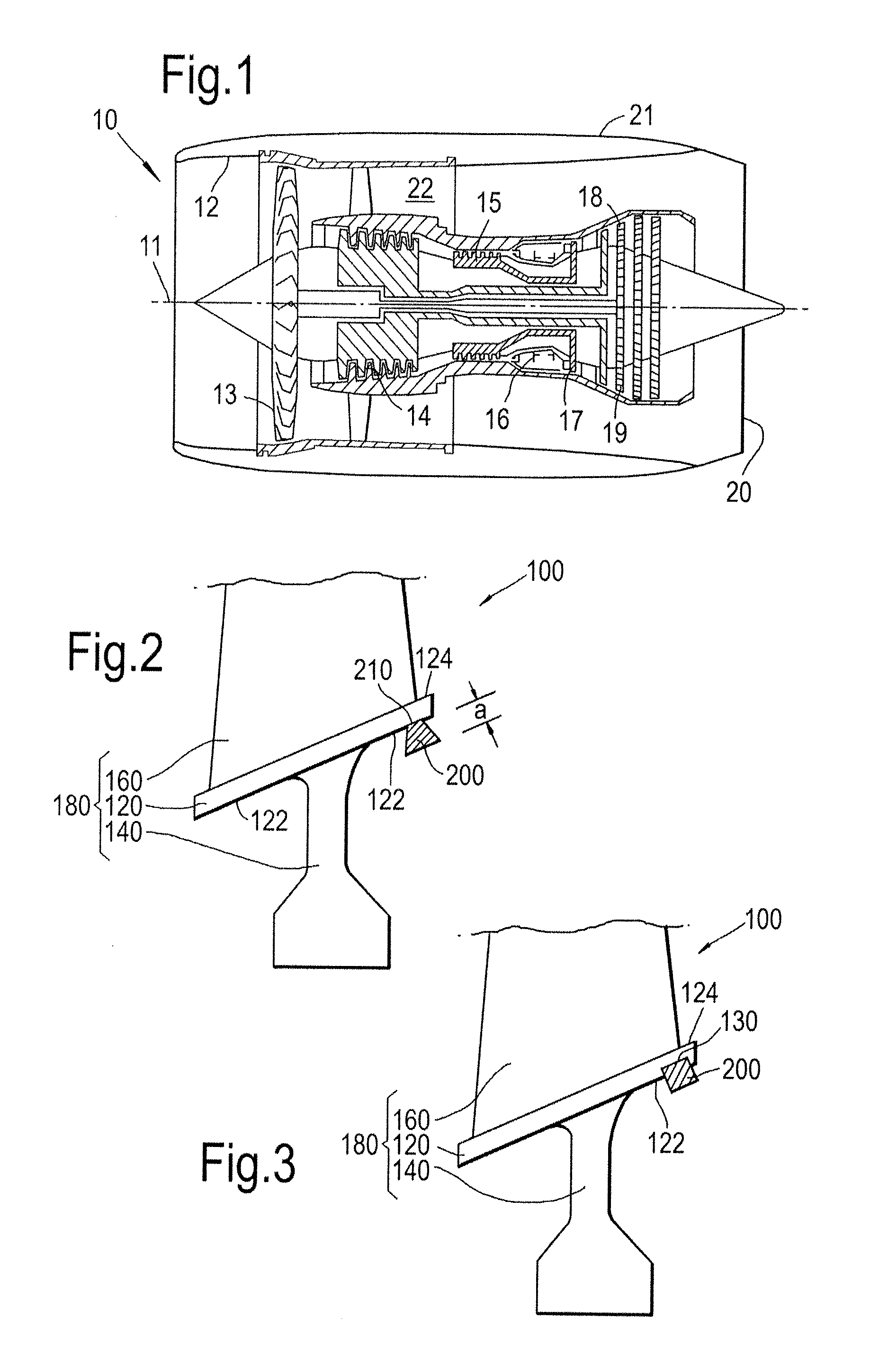
[0060]With reference to FIG. 1, a gas turbine engine is generally indicated at 10, having a principal and rotational axis 11. The engine 10 comprises, in axial flow series, an air intake 12, a propulsive fan 13, an intermediate pressure compressor 14, a high-pressure compressor 15, combustion equipment 16, a high-pressure turbine 17, and intermediate pressure turbine 18, a low-pressure turbine 19 and an exhaust nozzle 20. A nacelle 21 generally surrounds the engine 10 and defines both the intake 12 and the exhaust nozzle 20.

[0061]The gas turbine engine 10 works in the conventional manner so that air entering the intake 12 is accelerated by the fan 13 to produce two air flows: a first air flow into the intermediate pressure compressor 14 and a second air flow which passes through a bypass duct 22 to provide propulsive thrust. The intermediate pressure compressor 14 compresses the air flow directed into it before delivering that air to the high pressure compressor 15 where further com...


PUM


Abstract

A rotor stage of a gas turbine engine includes a platform from which rotor blades extend. The platform is provided with a circumferentially extending damper ring, the damper ring having an engagement surface that engages with the platform. The damper ring provides damping through slip between the engagement surface and the platform. The damper ring has a hoop stress that results in a load being provided to the platform from the engagement surface. The load can be optimized in order to provide improved damping.

Description

CROSS-REFERENCE TO RELATED APPLICATIONS[0001]This application is based upon and claims the benefit of priority from British Patent Application Number 1506196.3 filed 13 Apr. 2015, the entire contents of which are incorporated by reference.BACKGROUND[0002]1. Field of the Disclosure[0003]The present disclosure concerns a damper for a rotating part of a gas turbine engine.[0004]2. Description of the Related Art[0005]A gas turbine engine comprises various stages of rotor blades which rotate in use. Typically, a gas turbine engine would have at least one compressor rotor stage, and at least one turbine rotor stage.[0006]There are a number of ways in which the blades of a rotor stage may be attached to the engine. Generally, the blades attach to a rotating component, such as a disc, that is linked to a rotating shaft. Conventionally, blades have been inserted and locked into slots formed in such discs.[0007]Integral bladed disc rotors, also referred to as blisks (or bliscs), have also bee...

Claims


Application Information

Patent Timeline
Patent Type & Authority Applications(United States)
IPC IPC(8): F02C7/20F16F15/14
CPCF02C7/20F05D2260/96F05D2230/60F16F15/14F01D5/16F01D5/26F01D5/34F05D2240/80F05D2260/37F01D5/22
Inventor EDWARDS, GARRY MARK
Owner ROLLS ROYCE PLC
Why Eureka
Try Eureka