Modular engine, such as a jet engine, with a speed reduction gear

Active Publication Date: 2016-10-13
SN DETUDE & DE CONSTR DE MOTEURS DAVIATION S N E C M A
View PDF1 Cites 8 Cited by
  • Summary
  • Abstract
  • Description
  • Claims
  • Application Information

AI Technical Summary

Benefits of technology

This patent describes a modular engine made up of multiple modules. The invention proposes a solution to detach the means for fastening the drive means to the turbine shaft from the means for fastening the drive means to the journal, which solves the problem of modularity of the engine. Additionally, the invention includes a safety feature that allows for the removal of one module without risking the others being detached. This also ensures that lubricating oil is retained in the engine, which is beneficial during maintenance operations.

Problems solved by technology

Maintenance is particularly difficult on engines comprising a reduction gear in the front part.
In this case the problem is the accessibility of an internal nut of a turbine by which two major modules are connected to one another.

Method used


Image

  • Modular engine, such as a jet engine, with a speed reduction gear
  • Modular engine, such as a jet engine, with a speed reduction gear
  • Modular engine, such as a jet engine, with a speed reduction gear

Examples


Embodiment Construction

[0007]The present applicant has defined the object of the invention as the production of an engine having a reduction gear, which solves this problem of modularity.

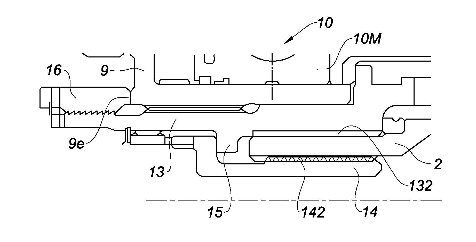
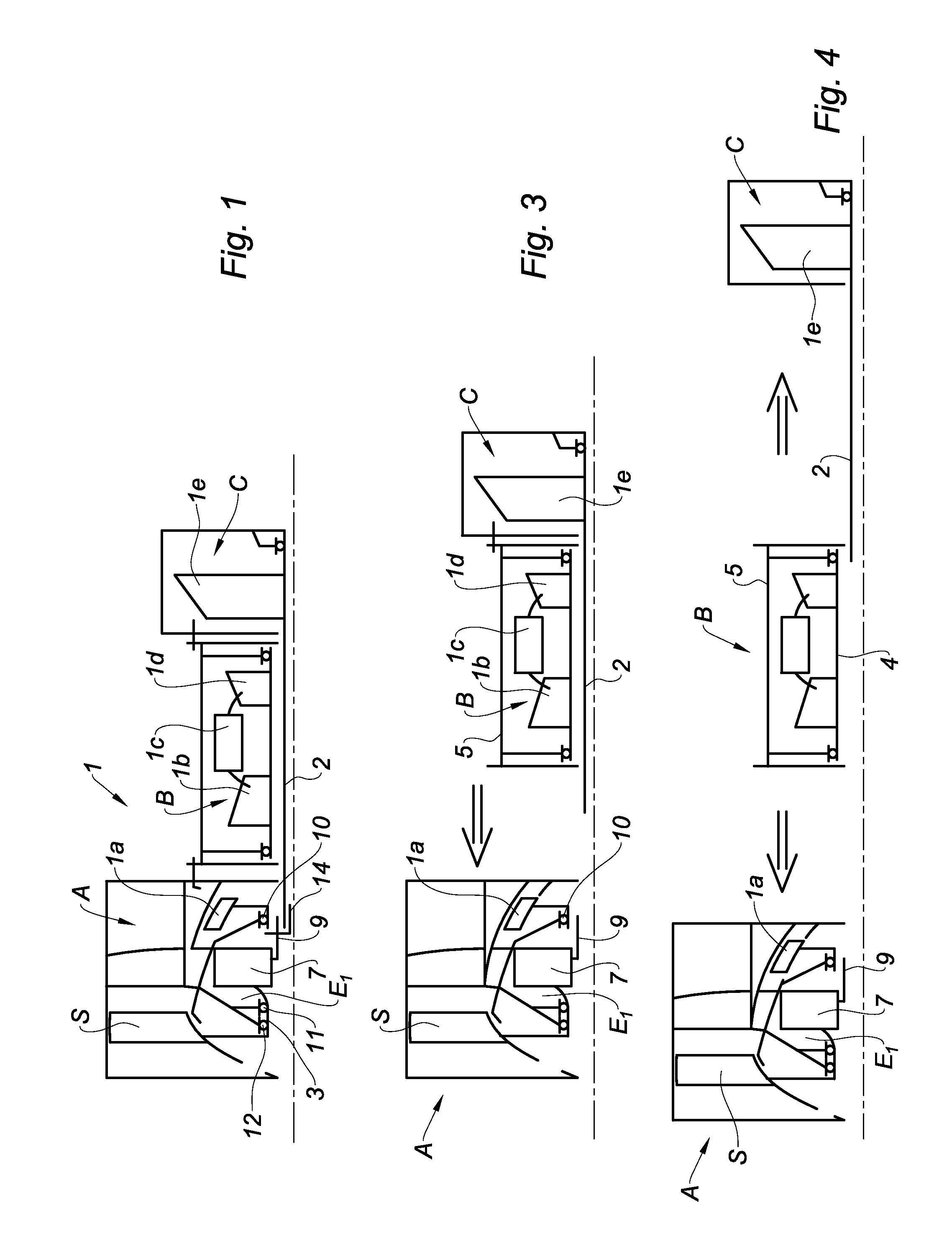
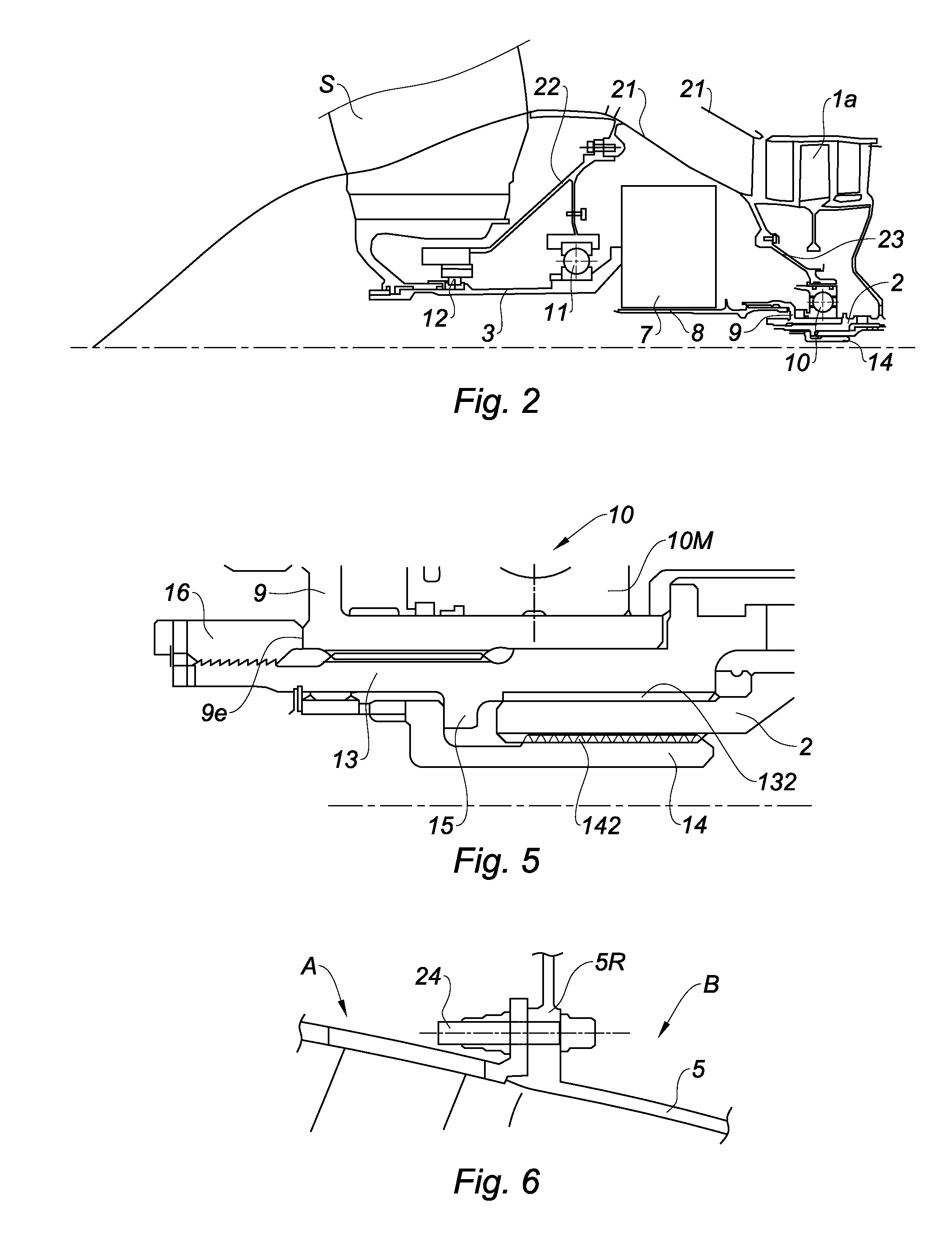
[0008]This object is achieved according to the invention by an engine having a modular structure, comprising a plurality of coaxial modules having, at one end, a first module comprising a power transmission shaft and a speed reduction gear, said power transmission shaft being driven via the speed reduction gear by a turbine shaft secured to one of said coaxial modules which is separate from the first module, the speed reduction gear comprising a drive means fastened to the turbine shaft and to a journal of a shaft of a low-pressure compressor rotor shaft, characterised in that it comprises a first nut for fastening the drive means to the journal and a second nut for fastening the drive means to the turbine shaft.

[0009]The speed reduction gear is preferably arranged in such a way that it has a central opening configured to...


PUM


Abstract

The present invention relates to an engine (1) with a modular structure comprising a plurality of coaxial modules (A, B, C) with, at one end, a first module (A) comprising a power transmission shaft (3) and a speed reduction gear (7), said power transmission shaft being driven via the speed reduction gear (7) by a turbine shaft (2) secured to one (C) of said coaxial modules that is separate from the first module, the speed reduction gear comprising a drive means (8 and 9) fixed to the turbine shaft (2) and to a journal (13) of a shaft of a low-pressure compressor rotor (1a), characterized in that it comprises a first nut (16) for fastening the drive means to the journal and a second nut (14) for fastening the drive means to the turbine shaft.

Description

FIELD OF THE INVENTION[0001]The present invention relates to an aircraft propulsion engine, such as a turbojet engine, a multi-flow turbofan, in particular with a high dilution ratio, or a turboprop engine, having a front power transmission shaft, driven by a turbine rotor by means of a speed reduction gear. In the case of a turbofan, the fan is mounted in particular on this power transmission shaft.PRIOR ART[0002]Turbofan engines have a plurality of compressor stages, in particular a low-pressure (LP) compressor, also referred to as a feed or booster compressor, and a high-pressure (HP) compressor, which belong to the main body of the engine. Upstream of the low-pressure compressor a large, movable-blade wheel or fan is disposed, which feeds both the primary flow which passes through the LP and HP compressors and the cold flow, or secondary flow, which is concentric with the first and is directed either directly towards a cold flow nozzle, referred to as a secondary nozzle, or towa...

Claims


Application Information

Patent Timeline
IPC IPC(8): F02C7/36F04D29/32F01D5/02F02K3/06F02C3/04
CPCF02C7/36F02K3/06F02C3/04F01D5/02F05D2240/60F04D29/325F05D2220/323F05D2240/35F04D29/321F01D5/025F01D5/026F02C7/32F05D2230/51F05D2230/60F05D2260/4031Y02T50/60
Inventor BRAULT, ROLAND GILBERT MICHELNOWAKOWSKI, NATHALIE
Owner SN DETUDE & DE CONSTR DE MOTEURS DAVIATION S N E C M A
Why Eureka
Try Eureka