Multi-fiber optical distribution cable for hallway installations

a technology of optical distribution cable and hallway installation, applied in the field of communication cables, can solve the problems of no procedure is optimal, negative visual impact, etc., and achieve the effect of reducing or eliminating the negative visual impact of cabl

Active Publication Date: 2016-10-13
OFS FITEL LLC
View PDF5 Cites 3 Cited by
  • Summary
  • Abstract
  • Description
  • Claims
  • Application Information

AI Technical Summary

Benefits of technology

[0014]According to the invention, an optical fiber distribution or breakout cable for servicing multiple customer units or premises in a multi-dwelling unit (MDU) building, includes a number of coated bend insensitive optical fibers each of which has a coating of a different color to identify the fiber. An outer jacket of a flame-retardant polymer compound is extruded to contain the coated fibers, and the jacket is sufficiently opaque to hide the colored fibers at least partially from view. The outer diameter of the jacket is not more than approximately 3.5 mm so that any negative visual impact of the cable is reduced or eliminated when the cable is installed over a routing path including a hallway wall to service the customer units or premises in the MDU building.

Problems solved by technology

In fact, potential customers will refuse installations only because the provider's cabling will have a negative visual impact.
Neither procedure is optimal, however.
Thus, in this case, all the colored fibers in the bundle will remain visible and contribute to the negative visual impact of the installation, especially if the bundle is routed over or near a lightly colored wall, ceiling, or molding.
Even if the units within the bundle are all of the same color, they can have a negative visual impact on installation due to the uneven surface of the bundle, resulting in some surfaces being shadowed.

Method used


Image

  • Multi-fiber optical distribution cable for hallway installations
  • Multi-fiber optical distribution cable for hallway installations
  • Multi-fiber optical distribution cable for hallway installations

Examples


example

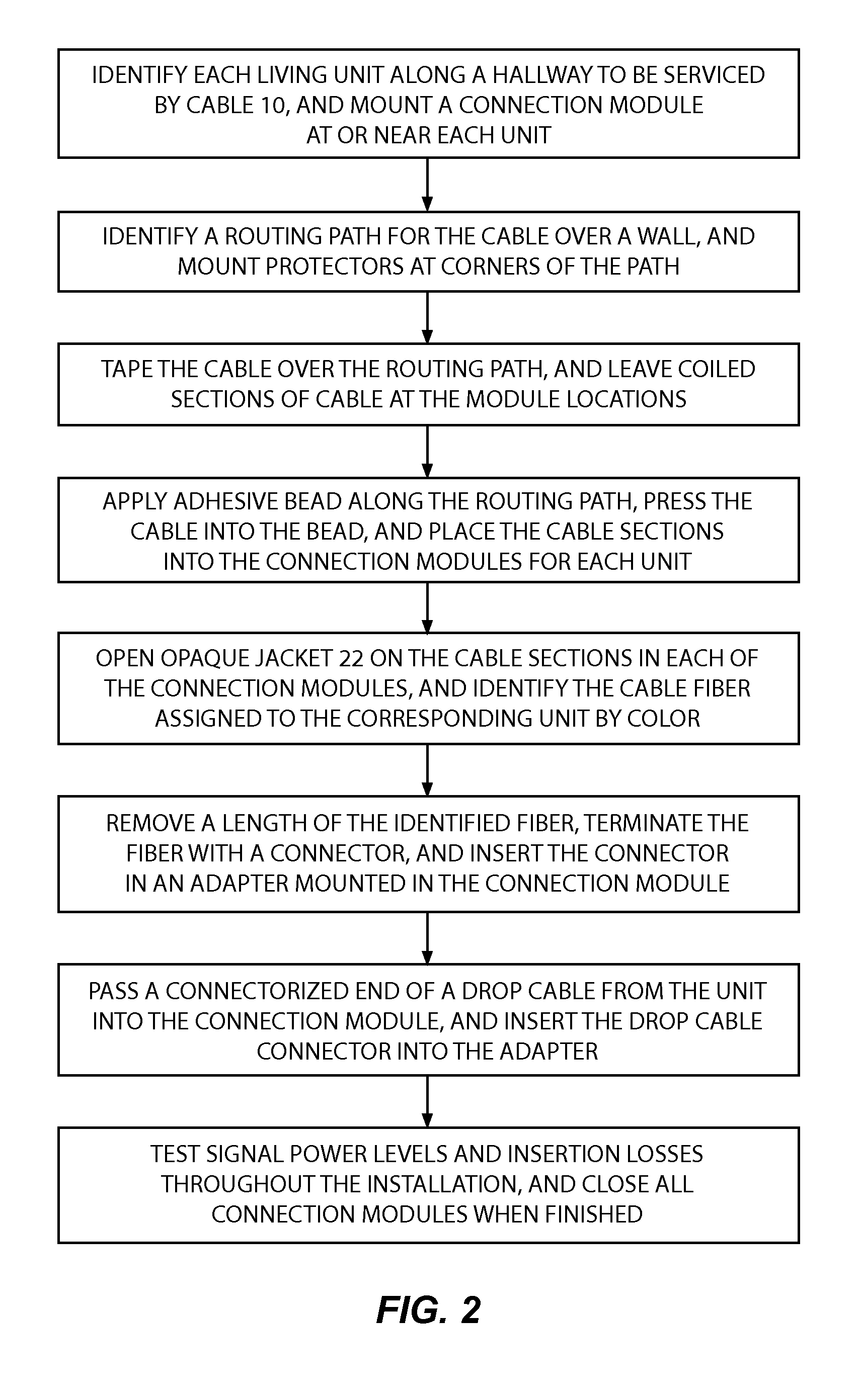
[0033]FIG. 2 shows an example of a hallway installation procedure for the cable 10 inside a MDU building, including the connection of the cable fibers to corresponding living units or premises along the hallway.

[0034]1. Identify all the living units or premises to be serviced by the cable 10. For each premises, determine a location on a wall of the hallway where a connection module can be mounted next to or near the premises, and secure the module in place. The module should be mounted as close as possible to the hallway ceiling, and overlie an opening through which an end of a terminated drop fiber can pass from inside the premises to enter the module. The connection module can be mounted either above the door of the living unit in the hallway, or, alternatively, inside the living unit near the door. To facilitate safe and fast wall penetrations, the module should not be mounted in the vicinity of a wall stud, or over wiring known to be present inside the wall.

[0035]2. Identify a r...


PUM


Abstract

An optical fiber distribution or breakout cable for serving multiple customer premises in a multi-dwelling unit (MDU) building. The cable contains a number of bend insensitive fibers each having a different colored coating for identification. A jacket of a flame-retardant polymer compound is extruded to surround the fibers. The jacket is sufficiently opaque to hide the color coated fibers at least partially from view, and the outer diameter of the jacket is not more than about 3.5 mm. A procedure for installing the cable through a hallway of a MDU building so as to lessen any negative visual impact of the installation on observers nearby is also disclosed.

Description

CROSS REFERENCE TO RELATED APPLICATION[0001]This application claims priority under 35 U.S.C. §119(e) of U.S. Provisional Patent Application No. 62 / 145,010 filed Apr. 9, 2015, titled “Low Visual Impact Multi-Fiber Microcord,” the entire contents of which are incorporated by reference.BACKGROUND OF THE INVENTION[0002]1. Field of the Invention[0003]The present invention relates to communication cables, and particularly to optical fiber distribution cables for servicing a number of different customer living units or premises in a multi-dwelling unit (MDU) building.[0004]2. Discussion of the Known Art[0005]Increasing amounts of optical fiber cabling are being installed annually to satisfy demand for fiber-to-the-home (FTTH) communication services by customers occupying living units or other premises in multi-dwelling unit (MDU) buildings. The services typically include, inter alia, television, telephony, and Internet access. Recent advances in optical fiber and cable technology have faci...

Claims


Application Information

Patent Timeline
Patent Type & Authority Applications(United States)
IPC IPC(8): G02B6/44G02B6/50
CPCG02B6/4466G02B6/4436G02B6/447G02B6/50G02B6/475G02B6/4482
Inventor BOXER, MARK A.HENDRICKSON, DANIELWEIMANN, PETER A.
Owner OFS FITEL LLC
Why Eureka
Try Eureka