Optical system of LED variable-focus imaging lamp

an imaging lamp and optical system technology, applied in lighting applications, lighting and heating apparatus, instruments, etc., can solve the problems of low lighting efficiency, low lighting intensity, and inability to adjust the light intensity and color temperature of the lamp prior art, so as to reduce the off-axis aberration, and imaging is clearer and sharper

Active Publication Date: 2016-10-13
GUANGZHOU HAOYANG ELECTRONICS CO LTD
View PDF7 Cites 2 Cited by
  • Summary
  • Abstract
  • Description
  • Claims
  • Application Information

AI Technical Summary

Benefits of technology

[0007]In the present invention, an incident plane of the first zoom lens of the zoom lens assembly adopts an aspheric structure. Its superficial radian is different from that of the ordinary spherical lens, so that the aberration may be well corrected. The diaphragm is an iris diaphragm with adjustable clear aperture, i.e. a vignetting diaphragm. This kind of diaphragm may reduce the off-axis aberration, so that the light beam from the off-axis point at the GOBO pattern, which could pass through the optical system, can only pass through partially. The off-axis stray light passing through is decrease, making the imaging clearer. In the stage imaging lamps, the present invention is the first invention to apply the aperture diaphragm to the zoom system of the imaging lamp, achieving advantages that the imaging is clearer and sharper. The problem to be solved in the present invention is, to design an optical system of variable-focus imaging on the basis of using LED module as light source and on the premise of achieving fittings sharing with the existing imaging lamp, with the zoom range continuously adjustable between 16°˜30°, which can substitute for a plurality of the existing fixed focus imaging lamps. The present invention provides an optical system of LED variable-focus imaging lamp which is smartly designed, has good performance and is practical and convenient.

Problems solved by technology

However, the halogen light source imaging lamp of the prior art is high in the whole lamp's heat, low in lighting efficiency, and the adjustments of the light intensity and the color temperature of which fail to be achieved.
In order to reduce cost and to achieve fittings sharing between LED imaging lamp and the existing imaging lamp using halogen bulb as light source, the diameter of the light spot of the focal point F of the imaging lamp is required to be between 60˜80 mm, which causes notable difficulty to the later lens design, so that many enterprises have to abandon the zoom system.
Although a few enterprises have designed the zoom system, the clarity of the patterns in the zoom process is not enough to meet the usage requirements.

Method used


Image

  • Optical system of LED variable-focus imaging lamp
  • Optical system of LED variable-focus imaging lamp
  • Optical system of LED variable-focus imaging lamp

Examples


embodiment

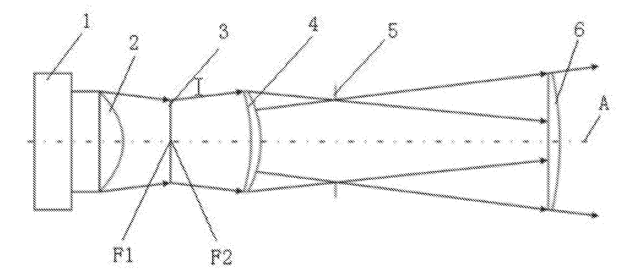
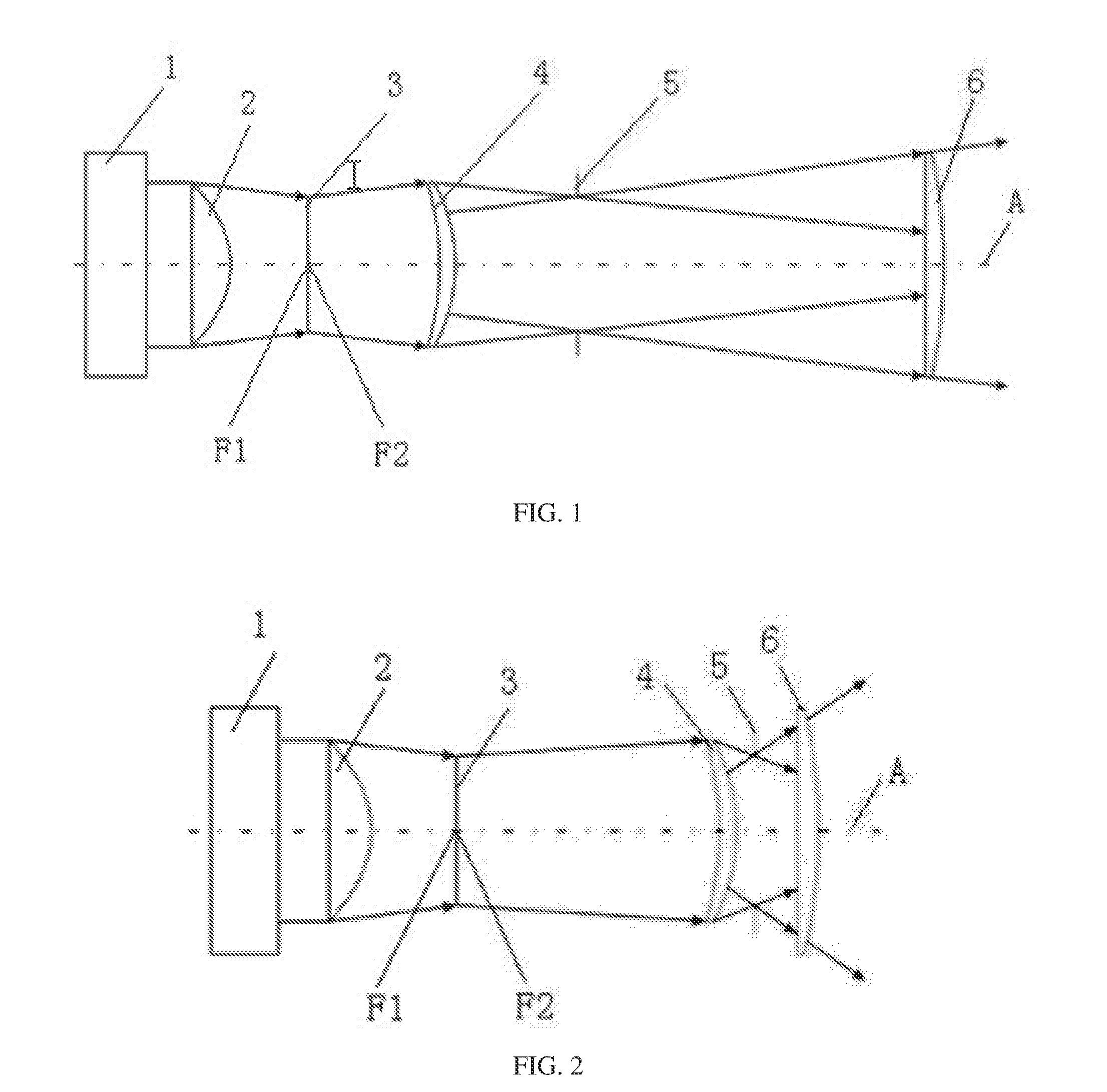
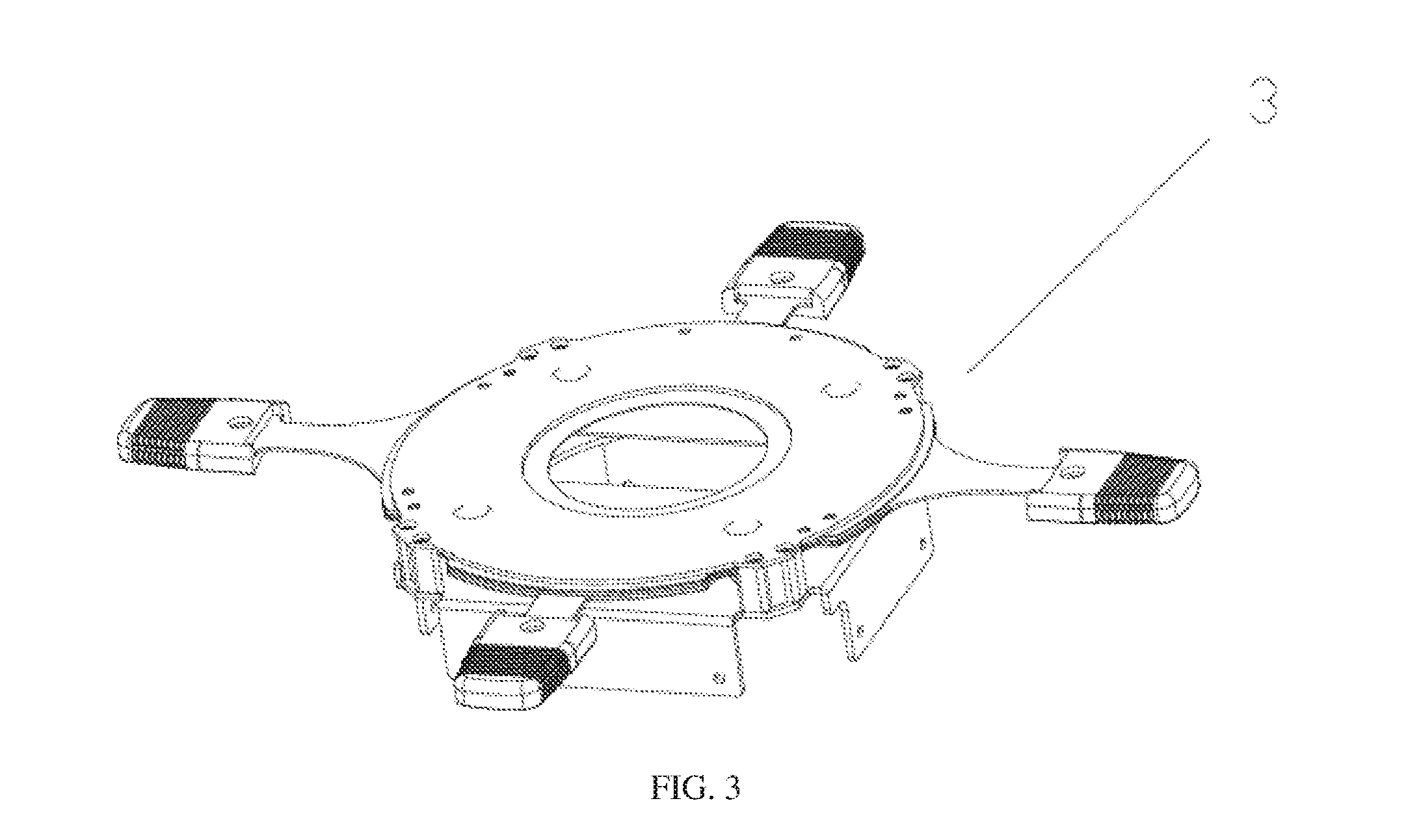
[0015]As shown in FIG. 1 and FIG. 2, an optical system of LED variable-focus imaging lamp of the present invention, comprises a LED light source module 1, a light-collecting assembly 2, a shutter assembly 3 and a zoom lens assembly, which are installed in sequence according to the direction of a light path. Geometry centers of the module and assemblies are collinear with a primary optic axis A. A focal point Fl of the light-collecting assembly 2 coincides with a focal point F2 of the zoom lens assembly. The zoom lens assembly comprises a first zoom lens 4, a diaphragm 5 and a second zoom lens 6. The first zoom lens 4 and the second zoom lens 6 move forward or backward along the direction of the primary optic axis A so that zoom is realized. The diaphragm 5 is disposed between the first zoom lens 4 and the second zoom lens 6, and the clear aperture of which is adjustable.

[0016]The zoom range of the zoom lens assembly is continuously adjustable between 16°˜30°.

[0017]An incident plane ...


PUM


Abstract

An optical system of LED variable-focus imaging lamp, comprises a LED light source module, a light-collecting assembly, a shutter assembly and a zoom lens assembly, which are installed in sequence according to the direction of a light path. Geometry centers of the module and assemblies are collinear with a primary optic axis A. A focal point F1 of said light-collecting assembly coincides with a focal point F2 of the zoom lens assembly. Said zoom lens assembly comprises a first zoom lens, a diaphragm and a second zoom lens. Said first zoom lens and the second zoom lens can move forward or backward along the direction of the primary optic axis A so that zoom is realized. Said diaphragm is disposed between the first zoom lens and the second zoom lens, and the clear aperture of which is adjustable.

Description

TECHNICAL FIELD[0001]The present invention relates to an optical system of LED variable-focus imaging lamp, which belongs to the innovative technology of the imaging optical system of LED imaging lamp.BACKGROUND[0002]The existing stage imaging lamps are classified into halogen light source imaging lamps and LED imaging lamps according to the light sources. However, the halogen light source imaging lamp of the prior art is high in the whole lamp's heat, low in lighting efficiency, and the adjustments of the light intensity and the color temperature of which fail to be achieved. To overcome the above defects of the halogen lamp, insiders in the industry have developed an imaging lamp using LED as light source. LED lamps have been widely used in various places of entertainment due to the advantages, such as energy conservation, environmental protection, high lighting efficiency, high brightness, long working life, strong controllability, etc. In order to reduce cost and to achieve fitt...

Claims


Application Information

Patent Timeline
Patent Type & Authority Applications(United States)
IPC IPC(8): G02B15/14G02B5/00F21V17/10G02B26/04F21V11/18F21V17/06G02B19/00G02B3/04G02B7/00
CPCG02B15/14G02B19/0066G02B5/005G02B3/04F21Y2115/10F21V11/186F21V17/06F21V17/104F21W2131/406G02B26/04G02B19/0019G02B15/142
Inventor JIANG, WEIKAI
Owner GUANGZHOU HAOYANG ELECTRONICS CO LTD
Why Eureka
Try Eureka