
Optimally designed aspheric myopia lens and preparation mold thereof

An optimized design, aspherical technology, applied in the field of myopia lenses, can solve the problems of aspherical lenses, the actual perception effect of the human eye is not as good, the assembly is difficult to ensure accuracy, and the theoretical wearing effect is affected, so as to increase wearing comfort, reduce weight, The effect of reducing volume and weight

Active Publication Date: 2021-09-21
SUZHOU MASON OPTICAL CO LTD +1
View PDF7 Cites 0 Cited by
  • Summary
  • Abstract
  • Description
  • Claims
  • Application Information

AI Technical Summary

Problems solved by technology

But in fact, in practical applications, it is difficult for many wearers to achieve these three points
The inclination angle of the frame will affect the theoretical wearing effect, and the bad habits of some wearers include the frame slipping up and down the bridge of the nose and there are frequent occurrences. Although the dotted pupil is an assembly requirement for aspheric lenses, not all optical shops will be carried out and the assembly itself is difficult to guarantee complete accuracy
Once the lens wearing position deviates, the actual perception effect of the aspheric lens may not be as good as that of the spherical lens without aberration correction.
The personalized aspheric lens with compensatory optimization design and precise assembly in the manufacturing factory for different wearing positions of individual glasses solves the problems caused by the influence of wearing position, but this kind of personalized lens cannot be mass-manufactured by mold casting , the cost of turning and ordering is very high, and the fitting method is relatively complicated and difficult to promote

Method used


Image

  • Optimally designed aspheric myopia lens and preparation mold thereof
  • Optimally designed aspheric myopia lens and preparation mold thereof
  • Optimally designed aspheric myopia lens and preparation mold thereof

Examples


Embodiment 1

[0031] This embodiment provides an aspherical myopia lens with a diopter of -4D, the refractive index of the lens material is 1.56, and the lens diameter is ∮80. The front surface of the spectacle lens adopts an even aspheric refraction surface, and the rear surface is a spherical refraction surface.

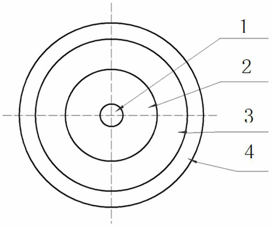
[0032] See attached figure 1 , is a structural schematic diagram of the aspheric myopia lens provided in this embodiment. The lens body is divided into four areas. The first area is the central photometric stability area 1, which is a circular area with a diameter of 5 mm; The axial aberration correction area 2 is an annular area with a diameter greater than 5 mm to 30 mm; the third area is the astigmatism control area 3, which is an annular area with a diameter greater than 30 mm to 66 mm; the fourth area is an annular area with a diameter greater than 5 mm to 30 mm; The annular area greater than 66 mm to the edge of the lens is the processing control area 4.

[0033] The opt...

Embodiment 2

[0059] This embodiment provides a lens whose diopter is -4D aspherical myopia lens, the refractive index of the lens material is 1.56, and the lens diameter is ∮80. The front surface of the spectacle lens is a spherical refraction surface, and the back surface is an even-numbered aspheric refraction surface.

[0060] The design method and design requirements are the same as those of Embodiment 1. According to the design requirements of the four partitions, this embodiment adopts ZEMAX programming to calculate and obtain the design parameters of the optimally designed aspheric myopia lens as shown in Table 3.

[0061] Table three:

[0062] .

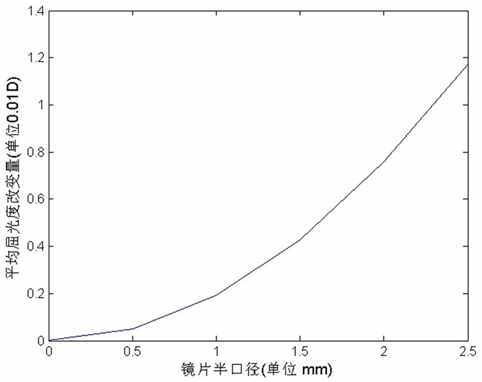
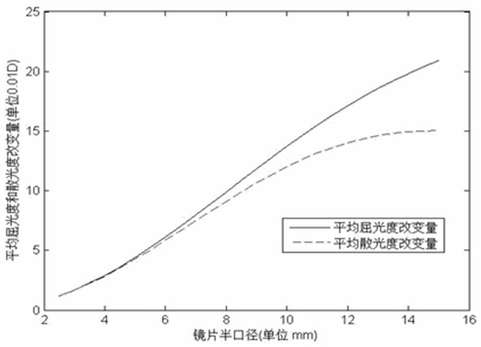
[0063] According to the design parameters in Table 3, using the ZEMAX program to calculate, within the scope of the first area, starting from the center of the lens, the diopter increases continuously; the change of the diopter at the center of the lens is zero, and the astigmatism is also zero. At the semi-diameter of 2.5mm (full-dia...

Embodiment 3

[0073] This embodiment provides a lens whose diopter is -4D aspherical myopia lens, the refractive index of the lens material is 1.56, the lens aperture is ∮80, and the front and rear surfaces of the lens are even-numbered aspheric refracting surfaces.

[0074] The design method and design requirements are the same as those of Embodiment 1. According to the design requirements of the four partitions, this embodiment adopts ZEMAX programming to calculate and obtain the design parameters of the optimally designed aspheric myopia lens, as shown in Table 5.

[0075] Table five:

[0076] .

[0077]According to the parameters in Table 5, using the ZEMAX program to calculate the average diopter change of the optimally designed aspheric myopia lens within the scope of the first area is as follows: the change of the average diopter at the center of the lens is zero, and the change in the semi-diameter of 2.5mm (full aperture 5mm), the average diopter change of the lens is 0.0054D. ...


PUM


Abstract

The invention discloses an optimally designed aspheric myopia lens and a preparation mold thereof. A spectacle lens body is divided into four areas, namely a central luminosity stable area with stable diopter change, an off-axis aberration correction area which adopts focal power compensation and controls an astigmatism value and an average diopter value, an astigmatism control area which reduces the astigmatism value as much as possible, and a processing control area which effectively controls stable change of rise and reduces edge thickness. The imaging quality of the aspheric myopia lens provided by the invention is superior to that of a myopia lens with the same luminosity in the prior art, and the aspheric myopia lens can improve the wearing comfort and reduce the influence that the actual wearing effect deviates from the theoretical design caused by the inclination angle of a spectacle frame, the wearing position of the frame spectacles and the bad habits of a wearer according to the use characteristics of the frame spectacles; meanwhile, the spectacle lens can be manufactured in batches through a mold, is convenient to process, reduces the cost, and is beneficial to further popularization and application of the aspherical lens.

Description

technical field [0001] The invention relates to a myopia lens, in particular to an optimized aspheric myopia lens which improves the wearer's comfort and a preparation mold thereof. Background technique [0002] The design of ordinary aspheric lenses often only considers the theoretical far-point spherical model of parallel light incidence. This design is only available when the point pupil assembly is correct, the wearer has good wearing habits, and the frame is parallel to the retina. In order to achieve the theoretical design effect. But in fact, in practical applications, it is difficult for many wearers to achieve these three points. The inclination angle of the frame will affect the theoretical wearing effect, and the bad habits of some wearers include the frame slipping up and down the bridge of the nose and there are frequent occurrences. Although dotted pupils are an assembly requirement for aspherical lenses, not all optical shops It will be implemented and the a...

Claims


Application Information

Patent Timeline
Patent Type & Authority Applications(China)
IPC IPC(8): G02C7/06
CPCG02C7/061
Inventor 余浩墨徐光华
Owner SUZHOU MASON OPTICAL CO LTD
Learn More