Undersea cable, undersea cable installation structure, and method for installing undersea cable

a technology for installing structures and cables, applied in the field of underwater cables, can solve the problems of difficult to securely obtain perfect impermeability with such impermeable layers, and achieve the effect of high impermeability and sufficient flexibility

Active Publication Date: 2016-10-13
FURUKAWA ELECTRIC CO LTD
View PDF6 Cites 9 Cited by
  • Summary
  • Abstract
  • Description
  • Claims
  • Application Information

AI Technical Summary

Benefits of technology

[0028]The present invention can provide an undersea cable and the like that can establish both sufficient flexibility and high impermeability.

Problems solved by technology

However, under the conditions where water pressure is applied, it is difficult to securely obtain a perfect impermeability with such impermeable layers.
Particularly when installed in deep water, it is sometimes impossible to obtain the required impermeability performance.

Method used


Image

  • Undersea cable, undersea cable installation structure, and method for installing undersea cable
  • Undersea cable, undersea cable installation structure, and method for installing undersea cable
  • Undersea cable, undersea cable installation structure, and method for installing undersea cable

Examples


Embodiment Construction

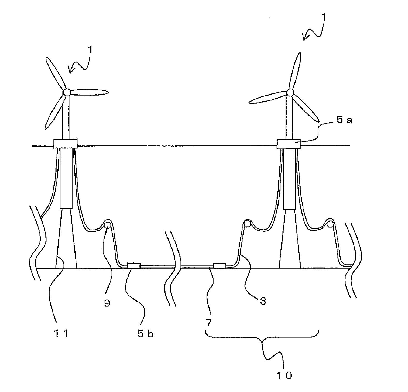
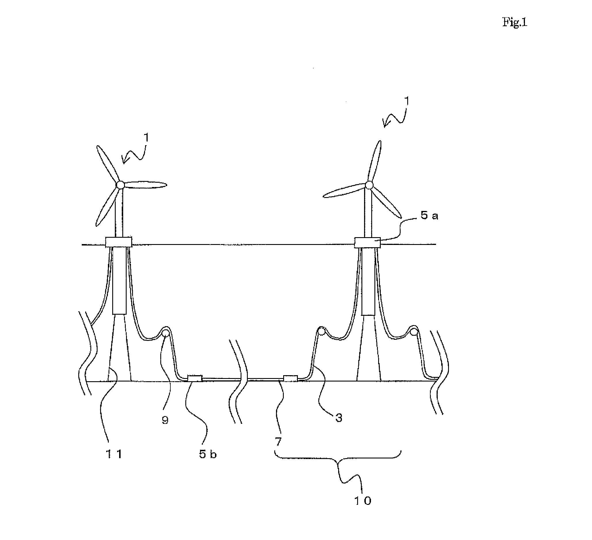
[0038]Hereinafter, an undersea cable and the like according to embodiments of the present invention will be described. FIG. 1 shows the installation state of an undersea cable 10. An ocean floating installation 1 is disposed on the sea. The ocean floating installation 1 is, for example, a floating type ocean wind power generator. The ocean floating installation 1 floats on the sea and the lower part thereof is fixed to the seabed with a mooring rope 11.

[0039]A plurality of the ocean floating installations 1 are disposed on the sea. Each of the ocean floating installations 1 is connected with a cable 3, which is a first cable, at a connection part 5a. Also, each of the cables 3 is connected with a cable 7, which is a second cable, at a connection part 5b. That is, the ocean floating installations 1 are connected with one another by the cables 3 and the cables 7.

[0040]A buoy 9 is connected between the connecting part 5a and the connecting part 5n of the cable 3. That is, a part of the...


PUM

PropertyMeasurementUnit
thicknessaaaaaaaaaa
thicknessaaaaaaaaaa
heightaaaaaaaaaa

Abstract

Ocean floating installations (1) are disposed on the ocean. The ocean floating installations (1) float on the ocean with the lower part of the ocean floating installations (1) being fixed to the seabed by mooring ropes (11). Each of the ocean floating installations (1) is connected at a connection part (5a) to a cable (3), which is a first cable. Each of the cables (3) is connected at a connection part (5b) to a cable (7), which is a second cable. In other words, the ocean floating installations (1) are connected to each other by the cables (3) and the cable (7). A connection is established with the cables (7) at the connection parts (5b) located on the seabed. In other words, the cables (7) are installed on the seabed.

Description

TECHNICAL FIELD OF THE INVENTION[0001]This invention relates to undersea cables and the like for ocean floating installations.BACKGROUND OF THE INVENTION[0002]In recent years, developments for renewable energy have been in progress as a countermeasure against global warming. For example, practical use of floating type off-shore wind power generators that transmit electricity from wind power generators, which are ocean floating installations, has been in progress.[0003]To transmit electricity from ocean floating installations, undersea cables are used. An undersea cable includes three power cables that are assembled and twisted together for three-phase alternating current power transmission and armoring wires provided on the periphery of the core to support the cable load.[0004]Since such undersea cables are laid under the sea, high impermeability is required for the internal power cables. Therefore, an impermeable layer is formed on the periphery of the insulator (shielding layer) i...

Claims


Application Information

Patent Timeline
Patent Type & Authority Applications(United States)
IPC IPC(8): H02G9/12H01B7/28H01B7/20H02G9/02H02G1/10H01B7/282H01B7/04
CPCH02G9/12H01B7/2825H01B7/2806H01B7/204H02G9/02H02G1/10H01B7/045F05B2240/93F05B2240/95F03D9/257Y02E10/727Y02E10/72
Inventor MANABE, HIROKIKAGOURA, TORUSASAKI, TAKAHIROSHIMADA, YOSHIHIROYAMAGUCHI, TAKEHARU
Owner FURUKAWA ELECTRIC CO LTD
Why Eureka
Try Eureka