Temperature regulated cabinet

a temperature-regulated cabinet technology, applied in the field of cabinets, can solve the problems of complicated product lines, high installation and operation costs, and difficult maintenance of the whole cabinet, and achieve the effect of improving the efficiency of external airflow circulation and saving power consumption

Active Publication Date: 2016-10-13
DELTA ELECTRONICS INC
View PDF6 Cites 25 Cited by
  • Summary
  • Abstract
  • Description
  • Claims
  • Application Information

AI Technical Summary

Benefits of technology

[0010]1. The temperature-regulated cabinet of the present invention comprises microcomputer controlled components including a first sensor, a second sensor, a third sensor and a controller, wherein the controller is provided for computing the temperature inside / outside a cabinet body and selecting the most appropriate operation mode for heat dissipation according to the ambient temperature to save the power consumption for the operation of a base station.
[0011]2. The temperature-regulated cabinet further comprises a suction fan which is turned on or off with an exhaust fan to improve the external airflow circulation efficiency of the temperature-regulated cabinet.

Problems solved by technology

The air conditioner is generally used as a cooling device in tropical zones, and the fan is generally used in cold zones for ventilation and heat dissipation, so that manufacturers need to prepare several different types of heat dissipations for the cabinet and face the issues of complicated product line and high installation and operation costs.
If the fan, heat exchanger and air conditioner are integrated into the same cabinet, and one of the fans, heat exchangers and air conditioners is damaged, users have to send the whole cabinet to factory for maintenance.
However, base stations are generally located at a remote place, and thus making the maintenance difficult and resulting in a long maintenance time.

Method used


Image

  • Temperature regulated cabinet
  • Temperature regulated cabinet
  • Temperature regulated cabinet

Examples


Embodiment Construction

[0020]The technical contents of the present invention will become apparent with the detailed description of preferred embodiments accompanied with the illustration of related drawings as follows.

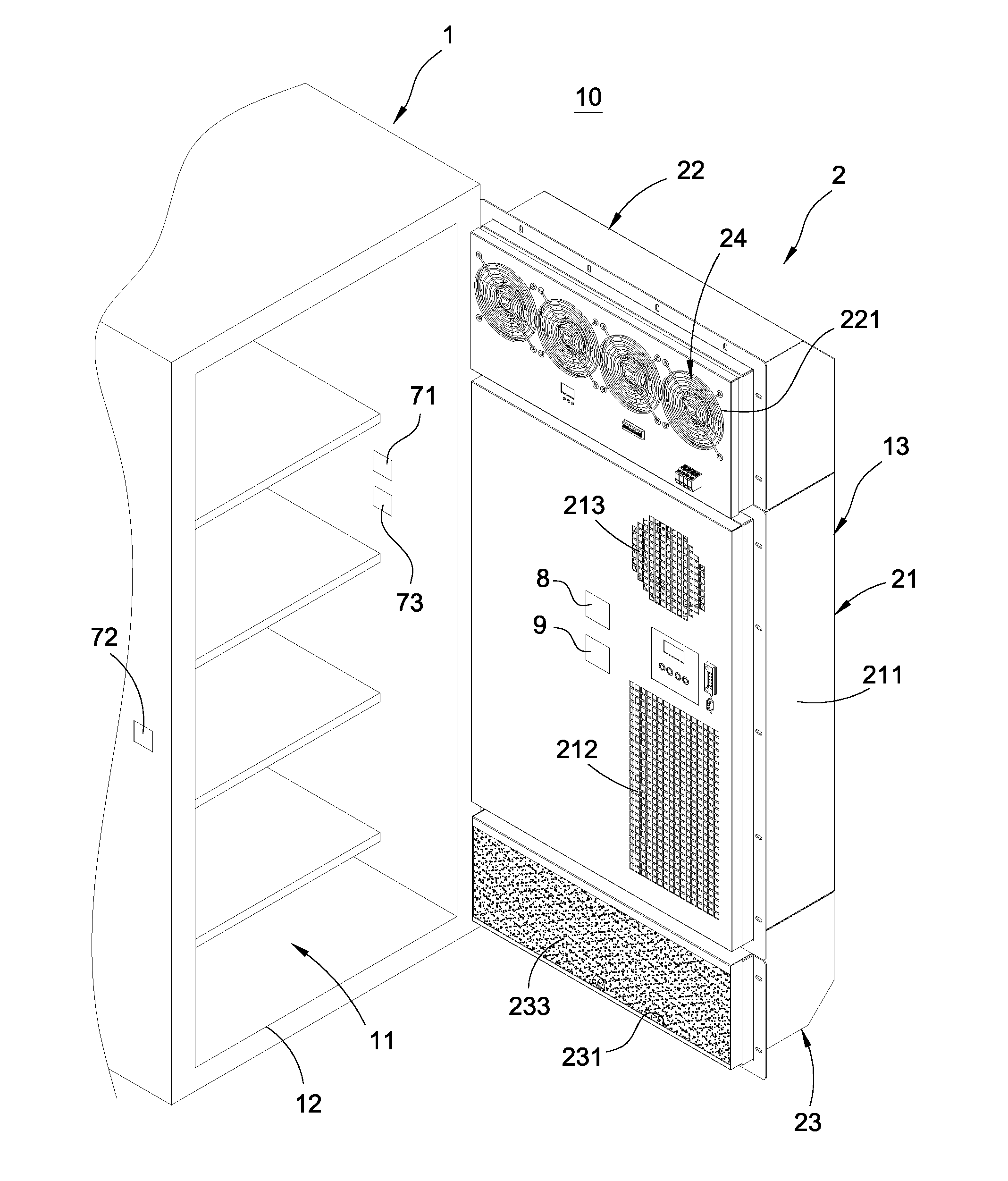
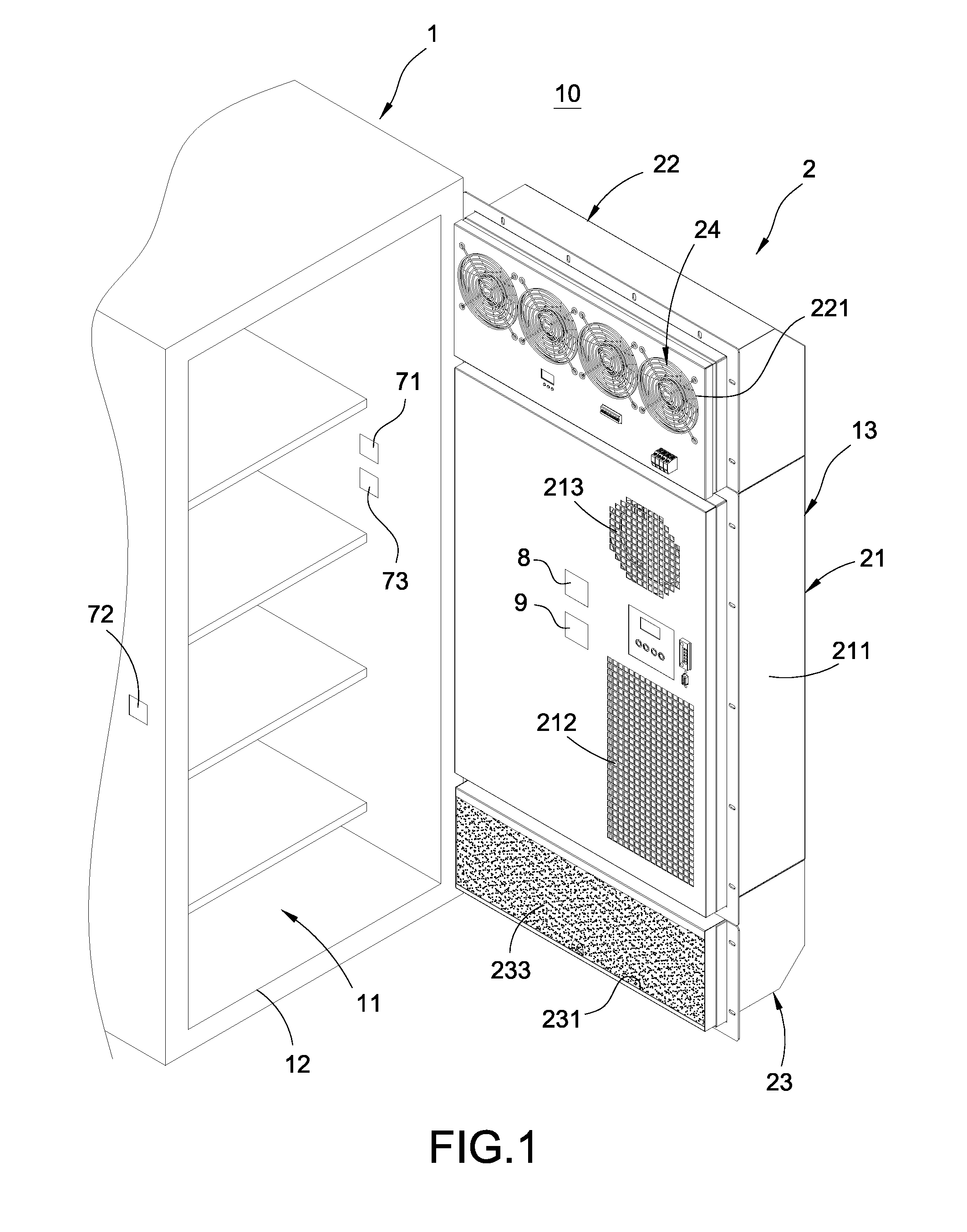
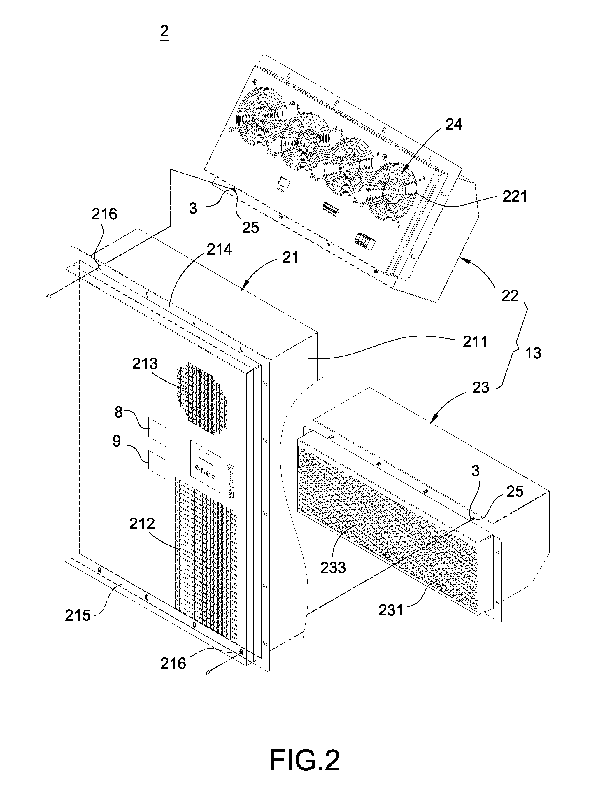
[0021]With reference to FIGS. 1 to 7 for a temperature-regulated cabinet of the present invention, the temperature-regulated cabinet comprises a cabinet body 1 and a temperature regulating module 2.

[0022]In FIG. 1, the cabinet body 1 may be a cold air conditioner, a hot air conditioner, a cold / hot air conditioner or a heat exchanger. The cabinet body 1 has a containing space 11 formed therein, and an opening 12 formed thereon and communicated with the containing space 11.

[0023]In FIGS. 1 to 7, the temperature regulating module 2 is detachably installed to the cabinet body 1 and covered onto the opening 12, and the temperature regulating module 2 comprises a temperature regulator 21, a first hood 22, a second hood 23 and one or more exhaust fans 24.

[0024]The temperature regulator 21 comprises...


PUM


Abstract

A temperature-regulated cabinet (10) includes a cabinet body (1) and a temperature regulating module (2). The cabinet body (1) has a containing space (11) formed inside the cabinet body (1) and an opening (12) communicated with the containing space (11). The temperature regulating module (2) is detachably installed to the cabinet body (1) and covered onto the opening (12) and includes a temperature regulator (21), a first hood (22), a second hood (23) and an exhaust fan (24). The temperature regulator (21) has a casing (211). The first hood (22) is detachably installed to the top of the casing (211), and the second hood (23) is detachably installed to the bottom of the casing (211). The exhaust fan (24) is installed inside the first hood (22) or the second hood (23). The cabinet has the advantages of simplifying the production line and lowering the construction and operation costs.

Description

FIELD OF THE INVENTION[0001]The present invention relates to a cabinet or enclosure of information equipments, and more particularly to a temperature-regulated cabinet.BACKGROUND OF THE INVENTION[0002]In a traditional information equipment cabinet (or enclosure), electronic equipments and devices such as electronic communication equipments, power converters or backup batteries are put inside the cabinet, and most cabinets are made of metal with dustproof and waterproof functions for isolating the electronic equipments and devices contained in the cabinet from the outside and preventing dust and rainwater from entering into the cabinet, so as to achieve the effect of protecting the electronic equipments and devices contained in the cabinet.[0003]In addition, the cabinet has a confined space formed therein. To dissipate the waste heat produced during the operation of the internal equipments, a fan or heat dissipating device is generally installed on the cabinet to maintain a low tempe...

Claims


Application Information

Patent Timeline
Patent Type & Authority Applications(United States)
IPC IPC(8): H05K7/20
CPCH05K7/207H05K7/20609H05K7/20554H05K7/20618
Inventor CHEN, LEE-LONGCHEN, CHIA-WEIWU, JIAN-JHANGHUNG, CHUN-YANG
Owner DELTA ELECTRONICS INC
Why Eureka
Try Eureka