Holder for fastening a fuel distributor to an internal combustion engine, and connecting method

a technology for fastening holder and fuel distributor, which is applied in the direction of liquid fuel feeder, machine support, machine/engine, etc., can solve the problems of low positioning accuracy of the bore of the screw mount, and thus the positioning accuracy of the fastening system, and limit the use of the known fuel apportioner with the fastening system. , to achieve the effect of improving the utilization range, improving the configuration and low manufacturing cos

Active Publication Date: 2016-10-20
ROBERT BOSCH GMBH
View PDF3 Cites 5 Cited by
  • Summary
  • Abstract
  • Description
  • Claims
  • Application Information

AI Technical Summary

Benefits of technology

[0004]The holder according to the present invention having the features of claim 1, the assemblage according to the present invention having the features of claim 9, and the connecting method according to the present invention having the features of claim 10 have the advantage that an improved configuration is made possible. In particular, large individual part tolerances can initially be enabled, but stringent demands in terms of predefined subassembly tolerances can then still be achieved. The result is an improved utilization range with low manufacturing costs.
[0009]It is advantageous that an aperture in which the fastening sleeve is placeable is provided on the fastening-means-side connecting segment; and that a positioning clearance, which, prior to connection of the fastening sleeve via the receiving part to the fastening-side connecting segment, allows positioning of the fastening sleeve in an axial direction of the fastening sleeve and / or in at least one radial direction of the fastening sleeve relative to the fastening-means-side connecting segment, is provided between the fastening sleeve and the aperture. This also allows the individual parts to be manufactured with larger tolerances. High accuracy can nevertheless be achieved thanks to a correspondingly accurate definition of the end positions of the individual parts. It is thereby possible, for example, to utilize for the manufacture of the individual parts manufacturing methods that as a rule are less accurate but are inexpensive. For example, stamped bent parts can be used. In particular, the holder can be configured as a stamped bent part. Cost-intensive post-processing of the individual parts can then be reduced and, if applicable, even entirely omitted.
[0012]It is also advantageous that a further receiving part is provided; that the further receiving part serves to connect the fastening sleeve to the fastening-means-side connecting segment of the holding element; and that the fastening-means-side connecting segment is disposed, for connection of the fastening sleeve to the fastening-means-side connecting segment, between the receiving part and the further receiving part. The receiving part and the further receiving part can in this context be configured identically. The receiving part and the further receiving part can, however, also be configured differently. For example, the receiving parts can be configured in disk-shaped fashion and can have different disk thicknesses and / or different outside disk diameters and / or different inside disk diameters. A greater load-carrying capacity for the connection between the fastening sleeve and the fastening-means-side connecting segment is then achievable by way of the two receiving parts.
[0013]It is advantageous that the receiving part has, on an outer side, an at least partly peripheral cutout. It is advantageous in particular that the receiving part has on the outer side an at least partly peripheral groove, if the fastening-means-side connecting segment is open toward the side. It is further advantageous here that, for connection of the fastening sleeve to the fastening-means-side connecting segment, the fastening-means-side connecting segment engages at its aperture into the cutout of the receiving part. A connection to the fastening-means-side segment and to the fastening sleeve can then be accomplished by way of the receiving part both on an upper side and on a lower side of the fastening-means-side connecting segment. Assembly is at the same time thereby simplified, since the number of components is reduced.
[0014]It is also advantageous that the fastening sleeve has a fastening segment on which the receiving part is disposed for connection of the fastening sleeve to the fastening-means-side connecting segment; and that the fastening sleeve is configured on the fastening-means-side connecting segment constrictedly relative to at least one end segment of the fastening sleeve. The result is that, for tight installation spaces, the fastening sleeve can be constricted at least in a center segment between the end segments with no change in the attachment diameters of the fastening sleeve. The geometry, in particular the outside diameter in the center segment, can thereby be made smaller while attachment diameters of the fastening sleeve remain the same. If the center segment of the fastening sleeve is configured constrictedly relative to both end segments, the fastening-means-side connecting segment is then configured to be open toward one side in order to enable introduction of the fastening sleeve.

Problems solved by technology

The fuel apportioner known from DE 10 2008 044 165 A1, and the fastening system, related thereto, of the fuel apportioner, have the disadvantage that the positioning accuracy of the bore of the screw mount, and thus also the positioning accuracy of the fastening system, is low.
The result is that tolerances for assembly must be allowed for, but these in turn lead to a positioning inaccuracy with regard to the fuel apportioner.
This limits possible use of the known fuel apportioner with this fastening system.

Method used


Image

  • Holder for fastening a fuel distributor to an internal combustion engine, and connecting method
  • Holder for fastening a fuel distributor to an internal combustion engine, and connecting method
  • Holder for fastening a fuel distributor to an internal combustion engine, and connecting method

Examples


Embodiment Construction

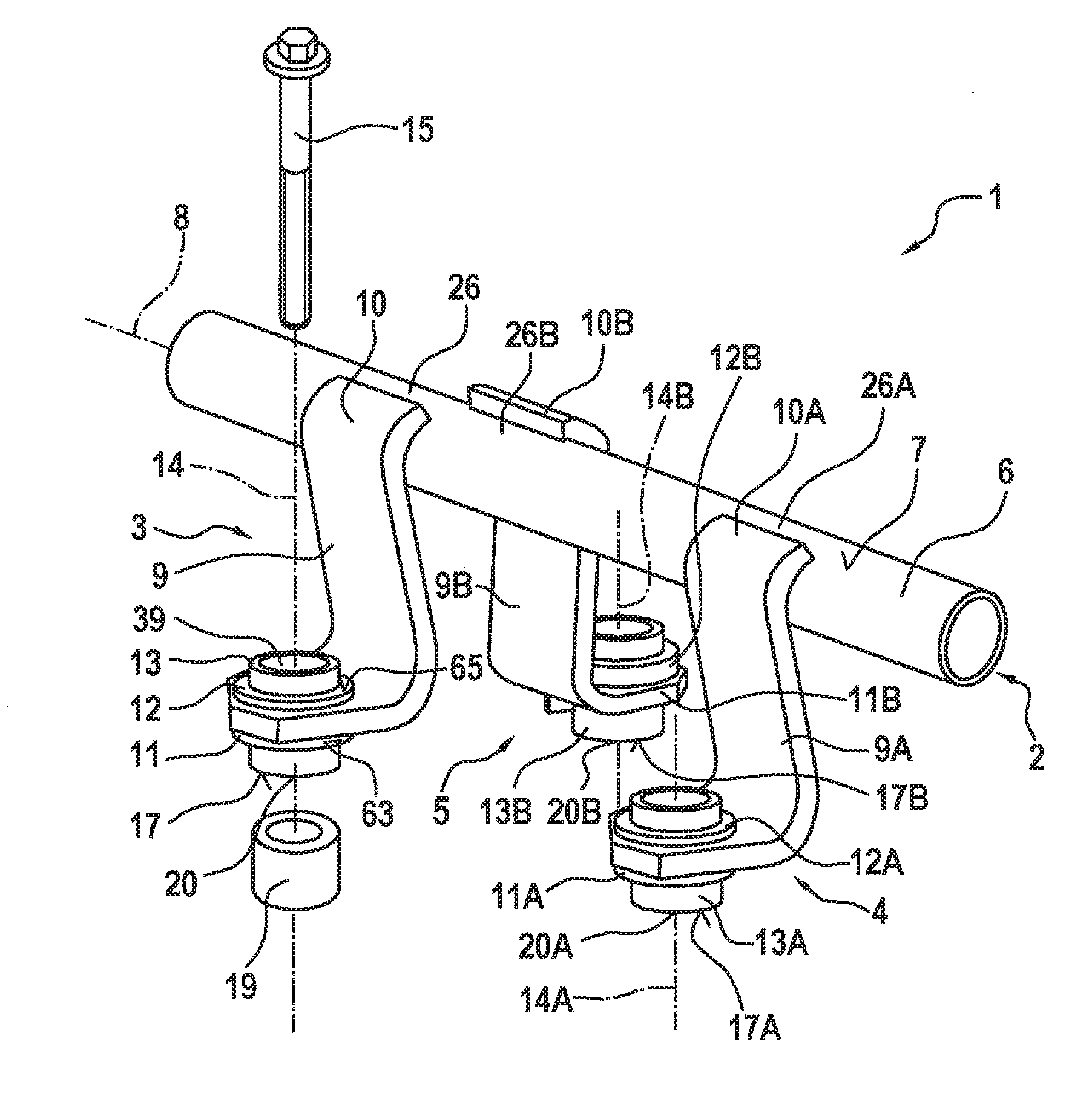
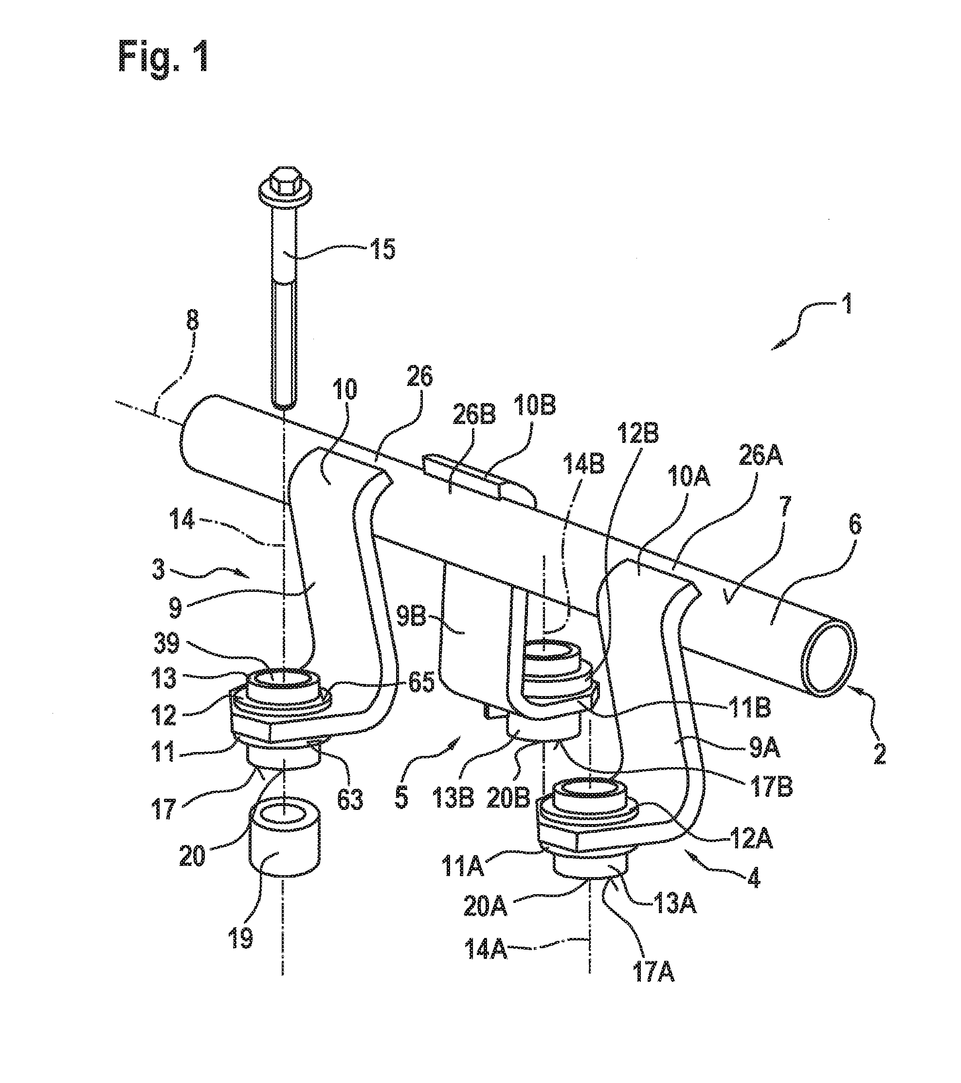
[0027]FIG. 1 is a schematic three-dimensional depiction of portions of an assemblage 1, having a component 2 and several holders 3, 4, 5, corresponding to a first exemplifying embodiment. Component 2 has a tubular base member 6 having an outer side 7 in the shape of a cylinder enveloping surface. Component 2 furthermore has a longitudinal axis 8 along which the tubular base member 6 extends. Component 2 can be configured, for example, as a fuel distributor. Suitable outputs, in particular cups, can be installed on the tubular base member 6 in order to distribute the delivered fuel to several fuel injection valves. In order to simplify the depiction, these outputs or cups are not shown.

[0028]Holder 3 has a holding element 9 having a component-side connecting segment 10 and a fastening-means-side connecting segment 11. Holder 3 furthermore has a receiving part 12 and a fastening sleeve 13. An axis serving as fastening axis 14 is defined by fastening sleeve 13. A fastening means 15, wh...


PUM


Abstract

A holder (3) serves for fastening a component (2), in particular a fuel distributor (2), onto an internal combustion engine (16). A holding element (9) that has a component-side connecting segment (10) is provided. The holding element (9) is connectable at the component-side connecting segment (10) to the component (2). The holding element (9) furthermore has a fastening-means-side connecting segment (11) at which the holding element (9) is fastenable via a fastening means (15) onto the internal combustion engine (16). A receiving part (12) and a fastening sleeve (13) are provided. The receiving part (12) serves to connect the fastening sleeve (13) to the fastening-means-side connecting segment (11) of the holding element (9). The fastening sleeve (13) has a through opening (39) through which the fastening means (15) is guidable. An assemblage (1) having such a holder (3) is also described. A connecting method is furthermore described.

Description

BACKGROUND OF THE INVENTION[0001]The present invention relates to a holder for fastening a component, in particular a fuel distributor, onto an internal combustion engine; to an assemblage having a component and such a holder; and to a connecting method for connecting a component that has a tubular base member to at least one holder. The invention relates in particular to the field of fuel injection systems of internal combustion engines.[0002]DE 10 2008 044 165 A1 discloses a fuel apportioner for an internal combustion engine having a housing. Attached to the fuel apportioner are several injection valves that inject fuel under high pressure into combustion chambers associated directly with them. A screw mount serves to fasten the fuel apportioner. An assembly screw is introduced into a bore of the screw mount. The shank of the assembly screw encompasses a respective annular-disk-shaped damping element on both sides of the screw mount. On the side facing away from the screw head the...

Claims


Application Information

Patent Timeline
Patent Type & Authority Applications(United States)
IPC IPC(8): F02M69/46F16M13/02F02M55/02
CPCF02M69/462F16M13/02F02M55/02F02M55/025F02M61/14F16B5/0225F02M2200/855F02M2200/857F02M2200/03F02M2200/8084F02M2200/26F02M2200/09F02M2200/306F02M63/0275
Inventor HAUG, MARTINLANG, KLAUSFROIHOFER, THOMAS
Owner ROBERT BOSCH GMBH
Why Eureka
Try Eureka