
Anti-Lash Assembly For Vehicle Power Steering

a technology for power steering and assembly, applied in mechanical devices, transportation and packaging, gearing, etc., can solve problems such as “lash” in the power steering assembly, and achieve the effect of reducing lash

Active Publication Date: 2016-10-20
TRW AUTOMOTIVE US LLC
View PDF0 Cites 3 Cited by
  • Summary
  • Abstract
  • Description
  • Claims
  • Application Information

AI Technical Summary

Benefits of technology

The patent text explains that one advantage of a new invention is that it reduces the movement of the steering wheel in a vehicle. This is useful because it helps improve the overall performance of the power steering system.

Problems solved by technology

Reversing the direction of travel for the rack member may result in “lash” in the power steering assembly.

Method used


Image

  • Anti-Lash Assembly For Vehicle Power Steering
  • Anti-Lash Assembly For Vehicle Power Steering
  • Anti-Lash Assembly For Vehicle Power Steering

Examples


second embodiment

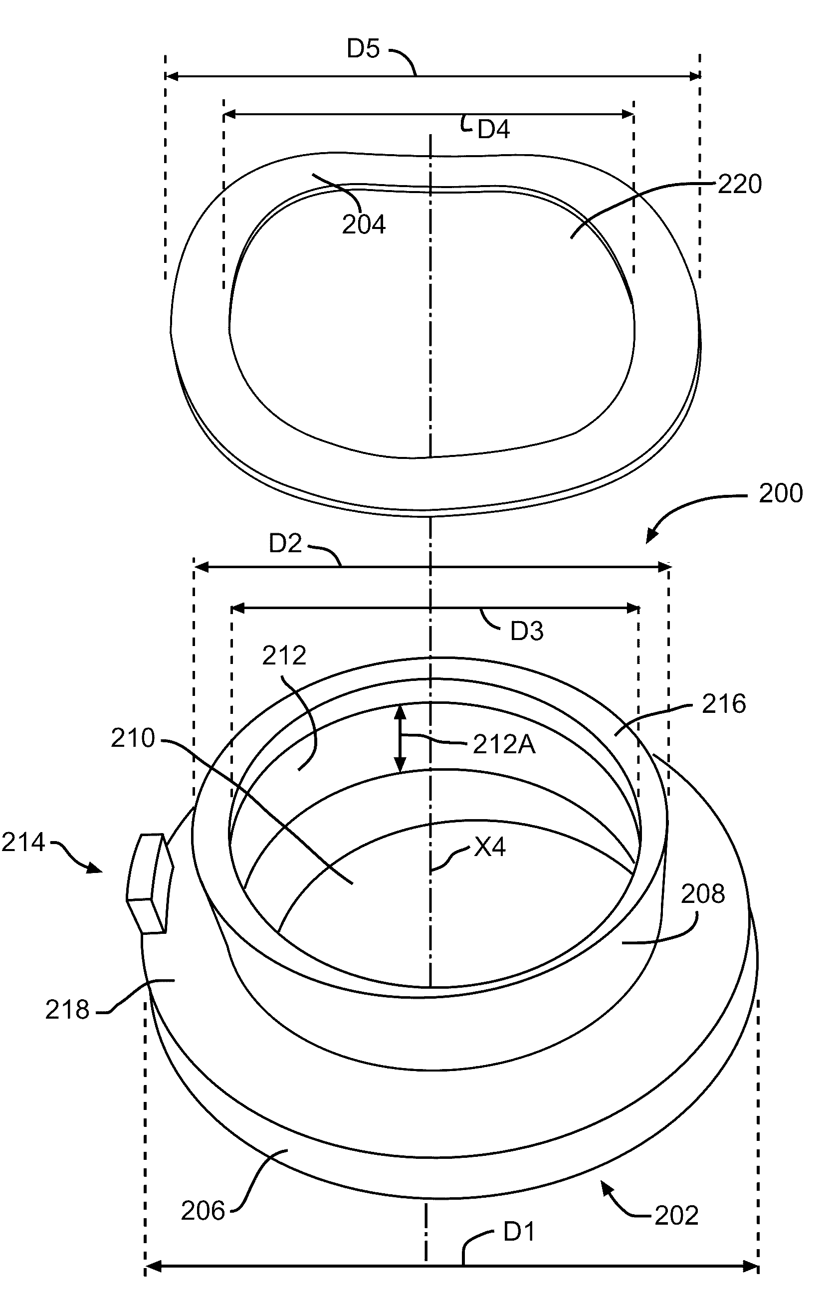
[0046]Referring now to FIG. 5, there is illustrated an anti-lash assembly, indicated generally at 500, produced in accordance with the present invention. Because the anti-lash assembly 500 is a variation of the anti-lash assembly 200 of FIGS. 3 and 4, like reference numerals, increased by 300, designate corresponding parts in the drawings and detailed description thereof will be omitted.

[0047]As shown in FIG. 5, using a suitable method known to those skilled in the art, the spring 504 may be fabricated to produce a moment about an axis perpendicular to the rack axis X2. For example, as illustrated, the spring 504 may be asymmetrical about the rack axis X2. The moment is produced as the bushing 502 is tightened and the spring 504 is compressed. The moment rotates the bushing 502 such that a first gap H1 on a first side 528 of the bushing 502 is less than a second gap H2 on a second side 530 of the bushing 502, the second side 530 being opposite the first side 528. The first gap H1 be...

third embodiment

[0048]Referring now to FIG. 6, there is illustrated a power steering anti-lash assembly, indicated generally at 800, produced in accordance with the present invention. Because the anti-lash assembly 800 is a variation of the anti-lash assembly 200 of FIGS. 3 and 4, like reference numerals, increased by 600, designate corresponding parts in the drawings and detailed description thereof will be omitted.

[0049]As shown in FIG. 6, the anti-lash assembly 800 has an alternative fastener 814 comprising a pin 836 between the bushing 802 and the ball nut 672. The pin 836 is conventional in the art and restrains the bushing 802 from rotating about the rack axis X2. For example, the pin 836 may have an enlarged head and be restrained by a cotter pin.


PUM


Abstract

A vehicle power steering assembly comprises a steering member having a screw portion. The screw portion has an external screw thread convolution with a first lead spacing. A ball nut is operatively connected to the screw portion. A bushing is operatively connected to the screw portion. The bushing has a bushing screw thread convolution with a second lead spacing. The second lead spacing is different than the first lead spacing. The bushing biases the ball nut against the screw portion.

Description

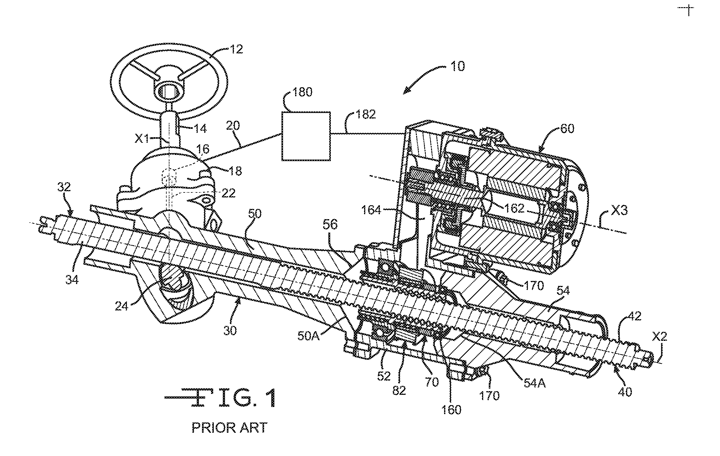
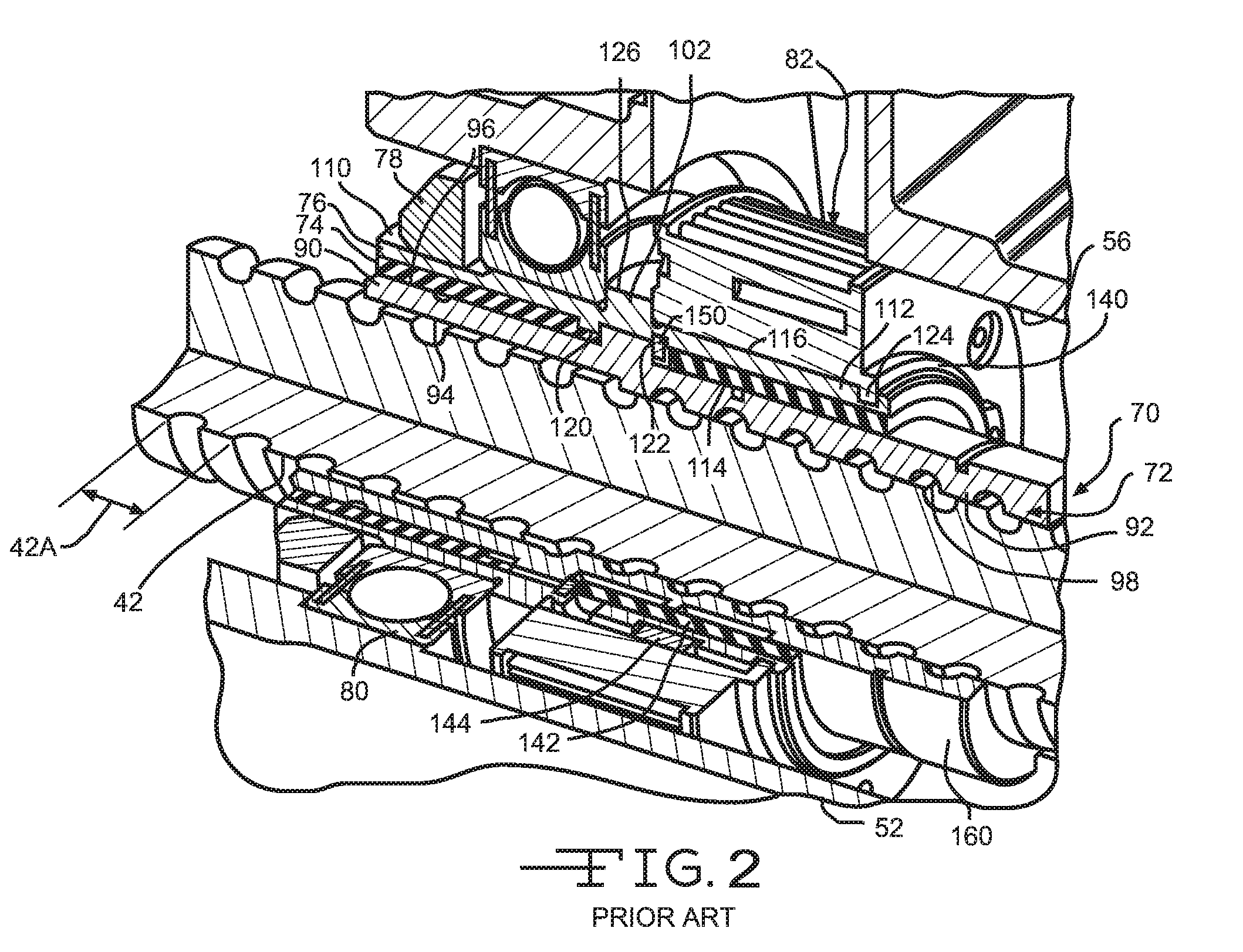
BACKGROUND OF INVENTION[0001]This invention relates in general to vehicle power steering assemblies and in particular to an anti-lash assembly for use in such a vehicle power steering assembly.[0002]One known power steering assembly for turning steerable wheels of a vehicle includes a ball nut for transmitting force between an axially movable rack member and a power source. For example, the power source may be an electric motor or hydraulic system. Upon actuation of the power source, the ball nut is driven to rotate relative to the rack member and the rotational force of the ball nut is transmitted to the rack member by balls that drive the rack member axially. The axial movement of the rack member by the balls effects turning movement of the steerable wheels.[0003]Turning movement of the steerable wheels is controlled by a driver rotating a steering wheel. Rotating the steering wheel activates the power source. When rotation of the steering wheel is reversed, both the rotational fo...

Claims


Application Information

Patent Timeline
Patent Type & Authority Applications(United States)
IPC IPC(8): F16H25/22B62D5/20B62D5/04
CPCF16H25/2209B62D5/20B62D5/0448B62D5/0421B62D5/0424F16H2025/2096
Inventor BEYERLEIN, JEFFREY
Owner TRW AUTOMOTIVE US LLC
Learn More