LED fluorescent lamp

a fluorescent lamp and led light technology, applied in the field of led fluorescent lamps, can solve the problems of inconvenient installation and maintenance, unfavorable working conditions of operating personnel under the lamp, etc., and achieve the effects of small light-emitting angle, easy damage to eyes, and reduced thermal radiation efficiency

Active Publication Date: 2016-10-20
LIN LAP WAH +1
View PDF2 Cites 9 Cited by
  • Summary
  • Abstract
  • Description
  • Claims
  • Application Information

AI Technical Summary

Benefits of technology

[0008]The beneficial effects of the invention are as follows: the LED lamp in the prior art has the disadvantages of small light-emitting angle, lower thermal radiation efficiency and blinding light, which directly shines into eyes and easily damages the eyes; this invention provides an LED fluorescent lamp; a first lamp panel and a second lamp panel are arranged on the aluminum profile in an oblique manner; the first lamp panel and the second lamp panel can make the light-emitting angle of the whole LED fluorescent lamp more than 180 degrees; the lamp shade is provided with a light diffusing plate, on which many crossed stripes are arranged to form diamond-shaped stripes; the light emitted by the LED lamp bead is reflected or refracted by the diamond-shaped stripes, so that shining light directly into people's eyes is avoided; meanwhile, the left side and the right side of the aluminum profile are provided with light guide plates; the upper surfaces of the light guide plates are coated with light reflecting layers capable of reflecting the incident light and increasing the illumination intensity of the LED fluorescent lamp; moreover, the light guide plates are rationally fixed on the aluminum profile to adjust the light-emitting angle of the LED lamp bead; the lower surfaces of the light guide plates are provided with wavy surfaces for increasing thermal radiation area; and the light guide plates combine with the aluminum profile to obtain a better thermal radiation effect.
are as follows: the LED lamp in the prior art has the disadvantages of small light-emitting angle, lower thermal radiation efficiency and blinding light, which directly shines into eyes and easily damages the eyes; this invention provides an LED fluorescent lamp; a first lamp panel and a second lamp panel are arranged on the aluminum profile in an oblique manner; the first lamp panel and the second lamp panel can make the light-emitting angle of the whole LED fluorescent lamp more than 180 degrees; the lamp shade is provided with a light diffusing plate, on which many crossed stripes are arranged to form diamond-shaped stripes; the light emitted by the LED lamp bead is reflected or refracted by the diamond-shaped stripes, so that shining light directly into people's eyes is avoided; meanwhile, the left side and the right side of the aluminum profile are provided with light guide plates; the upper surfaces of the light guide plates are coated with light reflecting layers capable of reflecting the incident light and increasing the illumination intensity of the LED fluorescent lamp; moreover, the light guide plates are rationally fixed on the aluminum profile to adjust the light-emitting angle of the LED lamp bead; the lower surfaces of the light guide plates are provided with wavy surfaces for increasing thermal radiation area; and the light guide plates combine with the aluminum profile to obtain a better thermal radiation effect.

Problems solved by technology

The above LED lamp is only applicable to be used in an environment with lower illumination intensity requirements; the light emitted by the LED lamp bead directly shoots out of the lamp shade, has a great influence on the eyes, and it is unfavorable for operating personnel to work under the lamp.
In addition, the above LED lamp is provided with screw holes on the lamp holder; the base is fixed to a ceiling through screws; the whole fixing base needs to be taken down during maintenance, and the installation and the maintenance are inconvenient.

Method used


Image

  • LED fluorescent lamp
  • LED fluorescent lamp
  • LED fluorescent lamp

Examples


Embodiment Construction

[0035]For a detailed description of the technical content, structural features, purpose, and effect of the invention, the following implementation mode and the drawings are utilized.

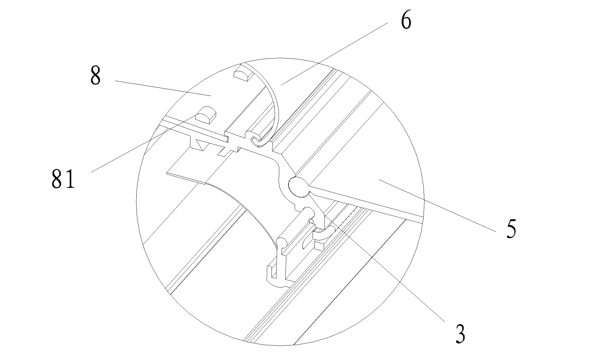
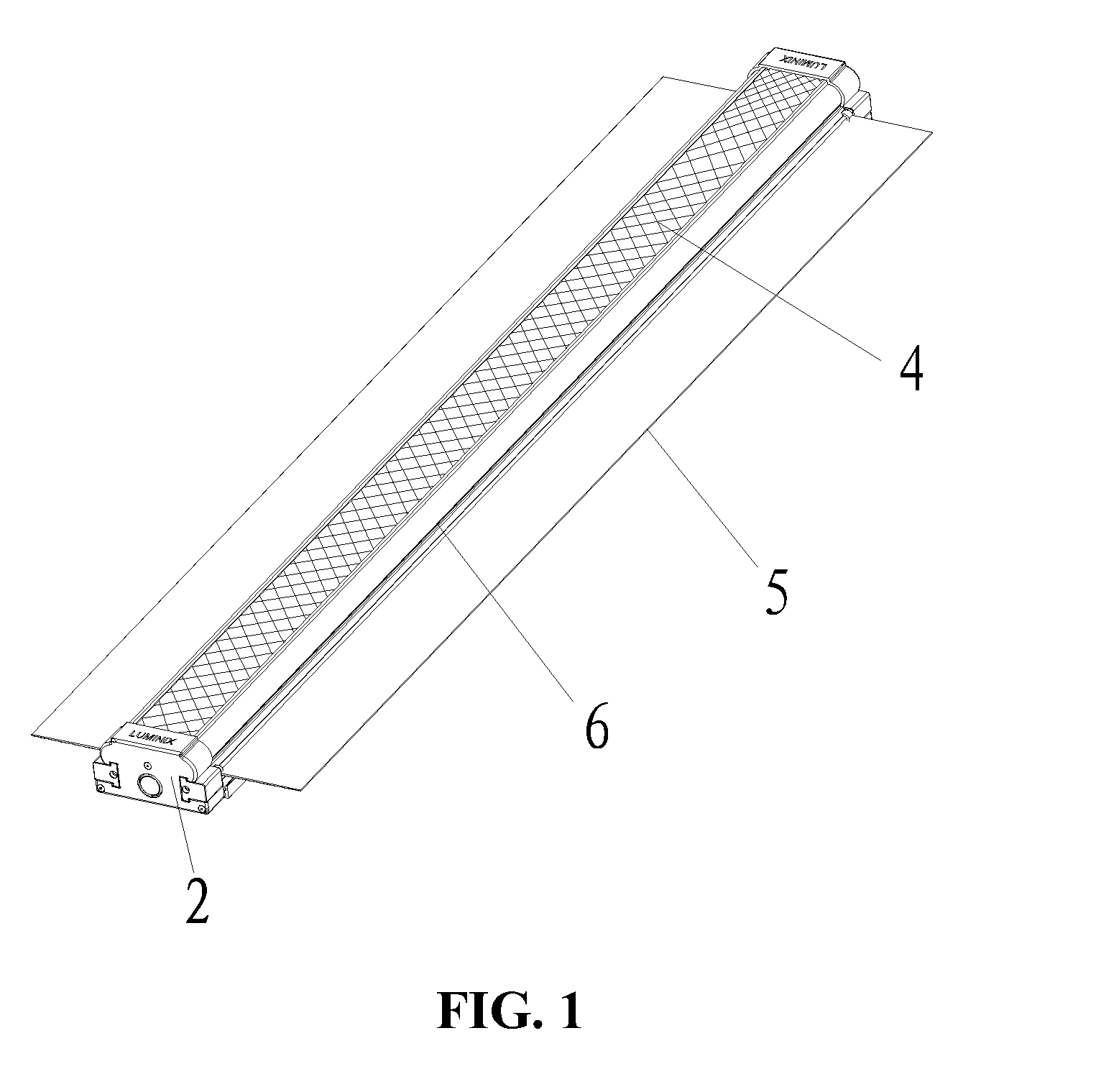
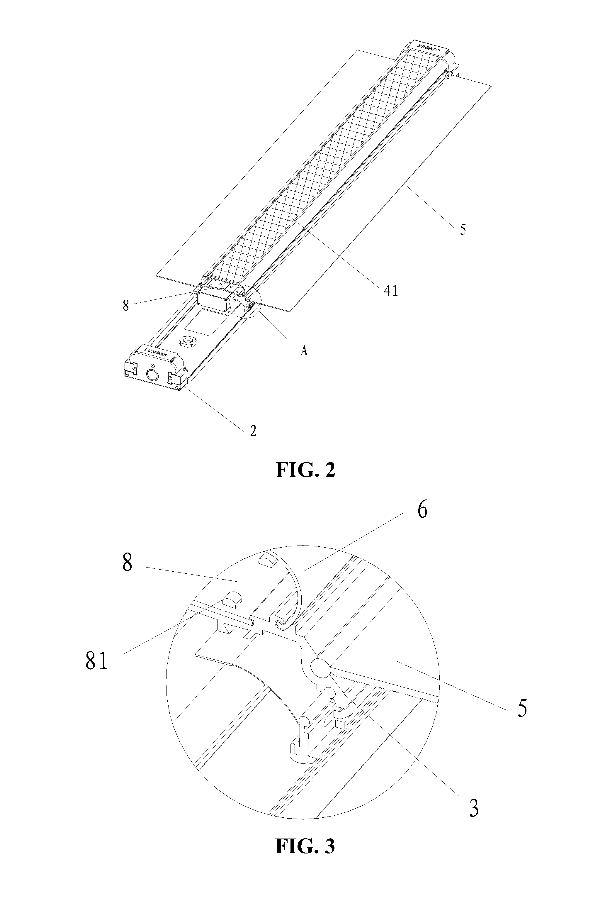
[0036]The key conception of the invention is as follows: the first lamp panel and the second lamp panel are arranged on the aluminum profile in an oblique manner, so that the light-emitting angle of the whole LED fluorescent lamp is more than 180 degrees; the lamp shade is provided with many crossed stripes, which are used for forming diamond-shaped stripes; the light emitted by the LED lamp bead is reflected or refracted by the diamond-shaped stripes, so that shining light directly into people's eyes is avoided; the upper surfaces of the light guide plates are coated with light reflecting layers capable of reflecting the incident light and increasing the illumination intensity of the LED fluorescent lamp; moreover, the light guide plates are rationally fixed on the aluminum profile to adjust the light-e...


PUM


Abstract

The invention discloses an LED fluorescent lamp, comprising a base plate, an end cap, an aluminum profile, a light diffusing plate, a light guide plate component, a lamp shade, a power unit and a lamp panel component as well as an LED lamp bead on the lamp panel component; first slots are arranged on two left side walls of the aluminum profile; the light guide plate can rotationally sleeved in the first slots; the top of the lamp shade is provided with a holding groove, at the bottom of which a hollowed-out part is hollowed out; the light diffusing plate is fixed in the holding groove and provided with many stripes on the surface; the stripes are crossed to form diamond-shaped stripes; and two sides of the lamp shade are arcs. The invention has the advantages of high thermal radiation effect, soft light and better light-emitting angle.

Description

TECHNICAL FIELD[0001]The invention relates to lighting equipment, in particular to an LED fluorescent lamp.DESCRIPTION OF THE RELATED ART[0002]An LED (Light Emitting Diode) is a solid semiconductor device capable of converting electric energy into visible light or directly converting electricity into light. The core of the LED is a semiconductor chip; one end of the chip is adhered on a bracket and is a negative electrode, and the other end is connected with the positive electrode of a power unit, so that the whole chip is encapsulated by epoxy resin. The LED lamp has the advantages of less energy consumption and good radial brightness, gradually replacing traditional incandescent lamps.[0003]The LED lamp in the prior art generally comprises a lamp holder, a radiator, a lamp panel, a lamp shade, and an LED lamp bead; the lamp holder, the radiator, and the lamp shade form a holding space; the lamp panel is fixed and closely joined to the radiator; the LED bead is installed on the lam...

Claims


Application Information

Patent Timeline
Patent Type & Authority Applications(United States)
IPC IPC(8): F21K99/00F21V23/02
CPCF21K9/17F21K9/52F21Y2101/02F21V23/02F21K9/50F21S8/00F21V3/049F21V17/02F21V29/70F21Y2115/10
Inventor LIN, LAP WAHCHAN, SEK LUN STEPHEN
Owner LIN LAP WAH
Why Eureka
Try Eureka