
Communication system, communication method, and control device

a communication system and control device technology, applied in the field of communication systems, can solve the problems of reducing the processing time of portable devices near the antenna, unable to meet the normal reception of rf signals by in-vehicle control devices, and requiring a longer period of time, so as to reduce the processing time.

Active Publication Date: 2016-10-20
ALPS ALPINE CO LTD
View PDF3 Cites 3 Cited by
  • Summary
  • Abstract
  • Description
  • Claims
  • Application Information

AI Technical Summary

Benefits of technology

The present invention is a communication system, method, and control device that can reduce delays in processing when multiple portable devices are transmitting signals to a control device. The invention uses a common period for all portable devices to transmit signals simultaneously, reducing the impact of individual signals. The control device can also quickly select an antenna for transmitting the request signal to the portable devices, improving communication quality. Additionally, the invention detects the strength of the received signal and compares it to a threshold value to reduce processing delays. Overall, this invention improves communication speed and reliability.

Problems solved by technology

However, in a case where a plurality of portable devices is registered in the in-vehicle control device, if RF signals for responding to the LF signal are transmitted from the plurality of portable devices so as to overlap each other in time domain, normal reception of the RF signals by the in-vehicle control device may not be possible.
However, this method has a problem in that as the number of registered portable devices is increased, a period of time required for determination of a state (non-existence state of the portable device) in which there is no portable device near to an antenna becomes longer.
That is, if reception processing is continuously performed until the last transmission period for all registered portable devices and thus it is finally confirmed that receiving the RF signal is not possible, conclusive determination of “the non-existence state of the portable device” is impossible.
However, even in the control system disclosed in Japanese Unexamined Patent Application Publication No. 2010-219628, the above-described problem in that as the number of registered portable devices is increased, the period for determination of “the non-existence state of the portable device” becomes longer is not solved.
That is, if response signals have been continuously received until an individual timing of the last portable device among all registered portable devices, conclusive determination of “the non-existence state of the portable device” is impossible.

Method used


Image

  • Communication system, communication method, and control device
  • Communication system, communication method, and control device
  • Communication system, communication method, and control device

Examples


Embodiment Construction

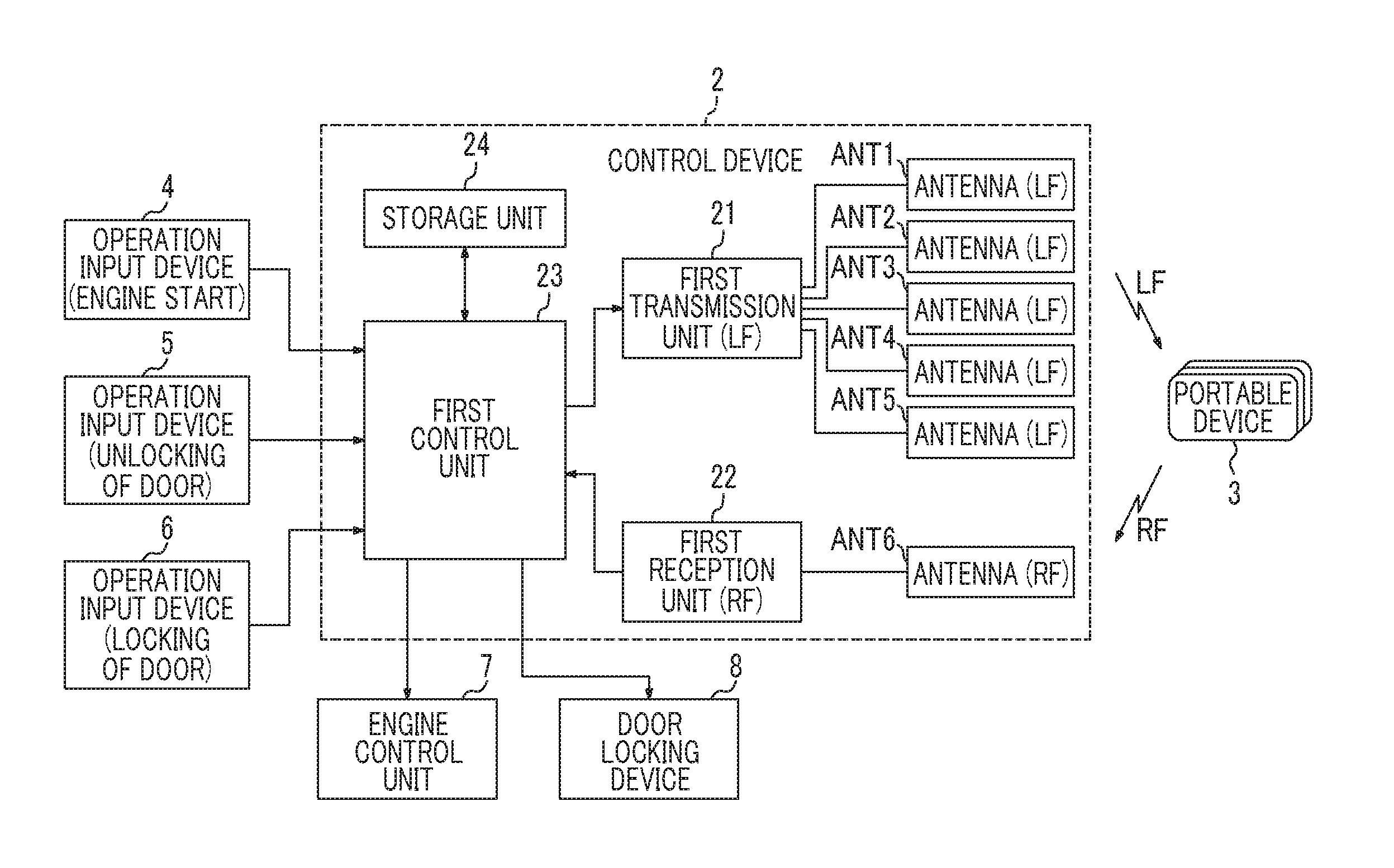
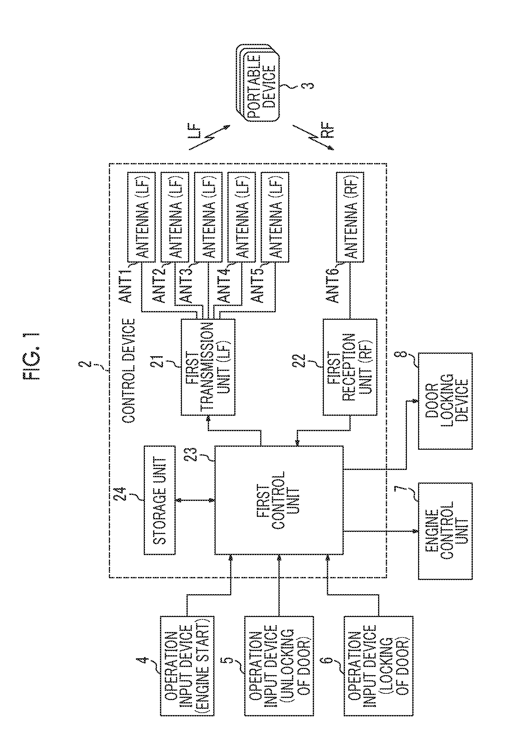
[0037]FIG. 1 is a diagram illustrating an example of a configuration of a communication system according to an embodiment of the present invention. The communication system illustrated in FIG. 1 is a passive•keyless entry system, and includes a control device 2 mounted in a vehicle 1, and a plurality of portable devices 3 which is held by a user and enables an operation.

[0038]The communication system illustrated in FIG. 1 is operated schematically as follows. First, if an operation input device (engine start button and the like) of the vehicle 1 is operated by a user who holds the portable device 3, a request signal in a LF band is transmitted to the portable device 3 from the control device 2 of the vehicle 1. If the portable device 3 receives the request signal, a response signal in a RF band is transmitted to the control device 2 from the portable device 3. The control device 2 performs authentication processing of determining whether or not the portable device 3 is a device whic...


PUM


Abstract

If a portable device receives a request signal from a control device that requires a response from the portable device, a first response signal is transmitted from the portable device during a common period defined in all portable devices. Thus, in a case where there is no portable device which enables wireless communication with the control device, a value of received signal strength indication of a wireless signal which is received from the portable device by the control device is very small and becomes smaller than the threshold value during a period in the common period. In this case, the control device suspends reception processing of causing a signal to be transmitted from the plurality of portable devices subsequently to the first response signal.

Description

CLAIM OF PRIORITY[0001]This application claims benefit of Japanese Patent Application No. 2015-082604 filed on Apr. 14, 2015, which is hereby incorporated by reference.BACKGROUND OF THE INVENTION[0002]1. Field of the Invention[0003]The present invention relates to a communication system in which wireless communication is performed between a control device mounted in a vehicle and a plurality of portable devices, that is, to the communication system such as a keyless entry system in which a door is locked or unlocked based on wireless communication between the in-vehicle control device and the portable device, for example.[0004]2. Description of the Related Art[0005]A keyless entry system is known in the related art (for example, see Japanese Unexamined Patent Application Publication No. 2010-219628). In the keyless entry system, an operation for a vehicle, such as locking or unlocking of a door of the vehicle, and a start of an engine is performed based on wireless communication bet...

Claims


Application Information

Patent Timeline
Patent Type & Authority Applications(United States)
IPC IPC(8): G07C9/00
CPCG07C9/00309G07C2009/00769G07C9/00007H01Q1/3291H04B7/0604H01Q1/3241H01Q21/29G07C9/20
Inventor SAMPEI, YOSHIO
Owner ALPS ALPINE CO LTD
Learn More