Spinning bike equipped with a sensor device

Inactive Publication Date: 2016-10-27
DK CITY CORP
View PDF4 Cites 24 Cited by
  • Summary
  • Abstract
  • Description
  • Claims
  • Application Information

AI Technical Summary

Benefits of technology

[0008]It is the primary objective of the present invention

Problems solved by technology

However, the conventional magnetic resistance device is not equipped with an

Method used


Image

  • Spinning bike equipped with a sensor device
  • Spinning bike equipped with a sensor device
  • Spinning bike equipped with a sensor device

Examples


Embodiment Construction

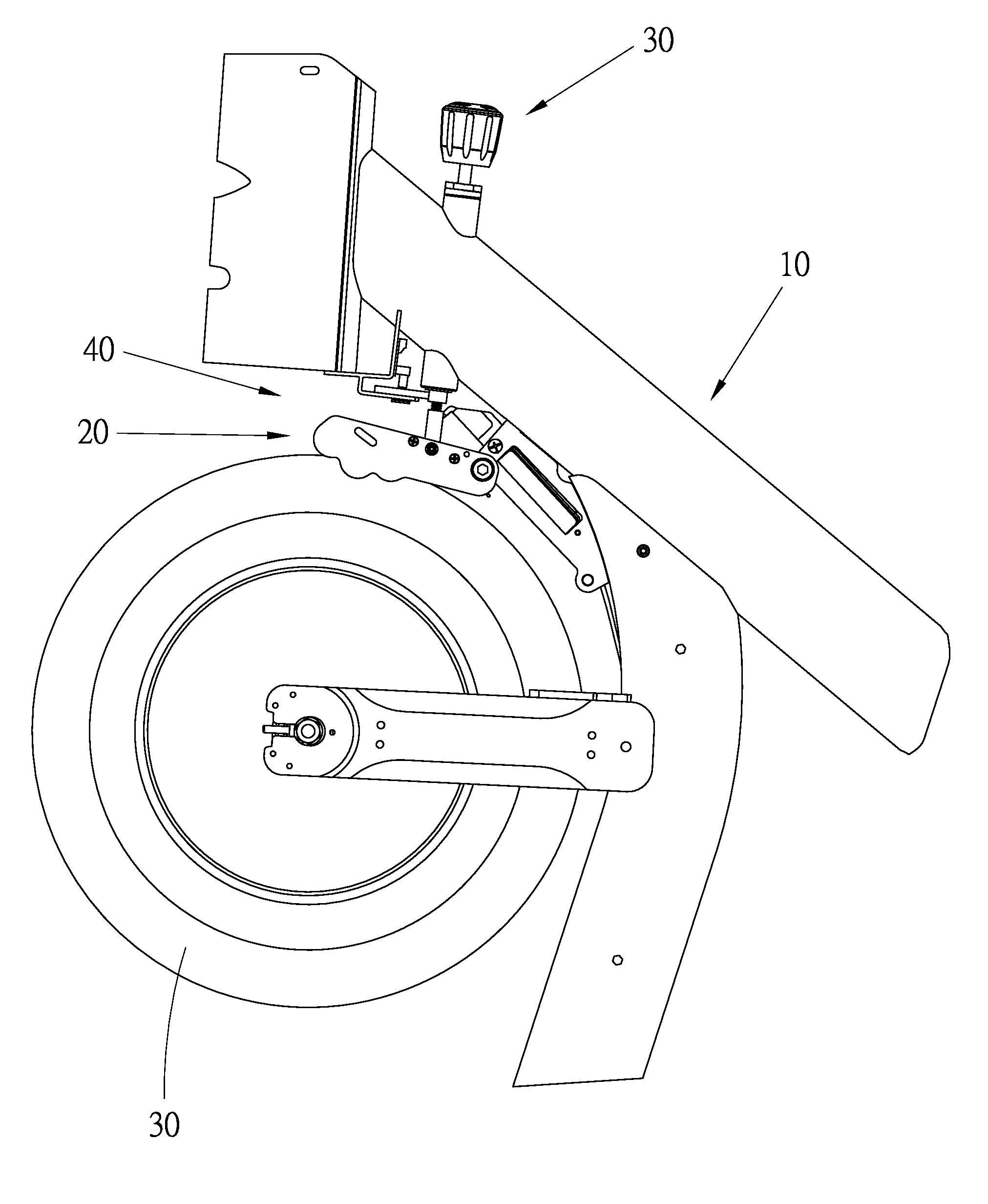
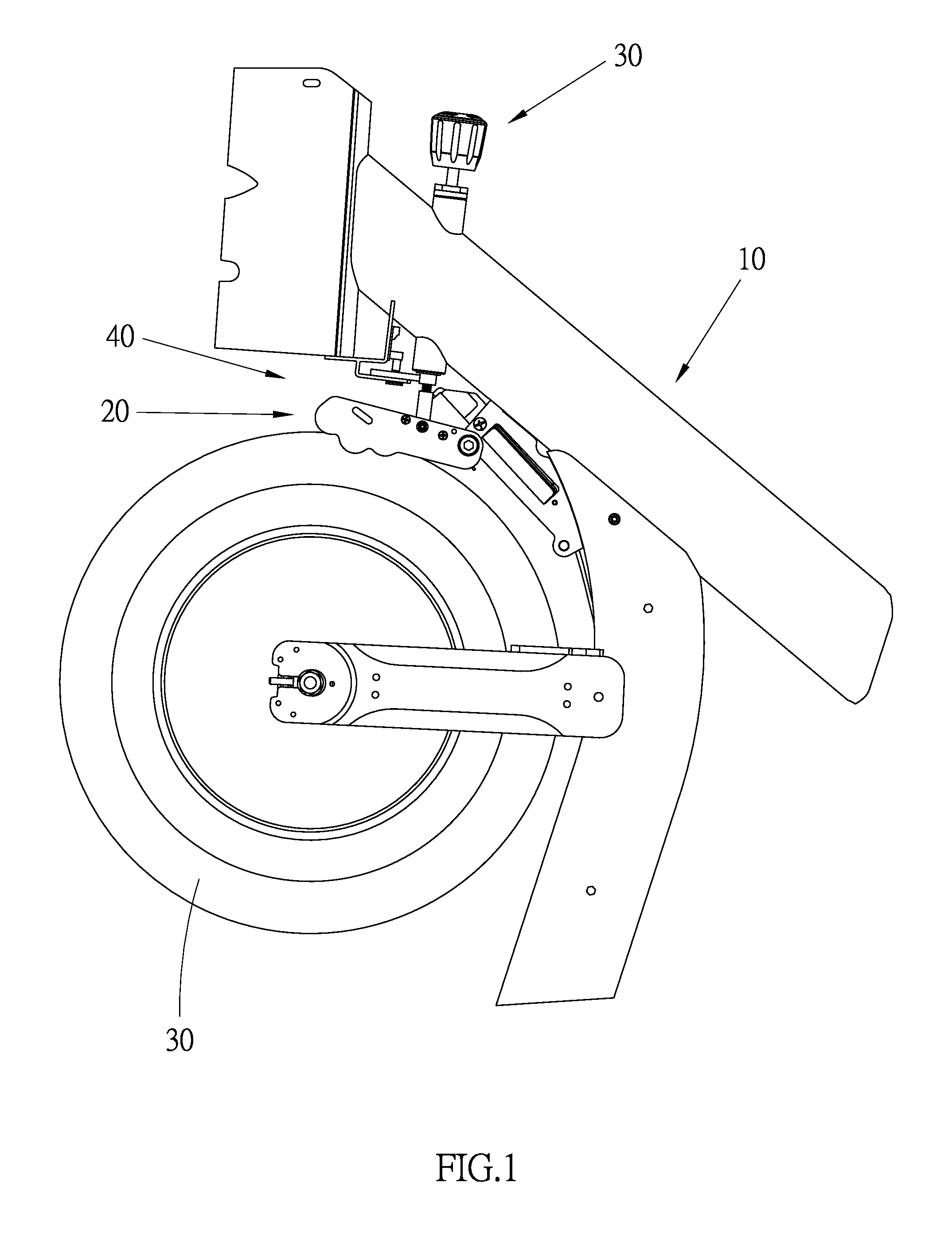
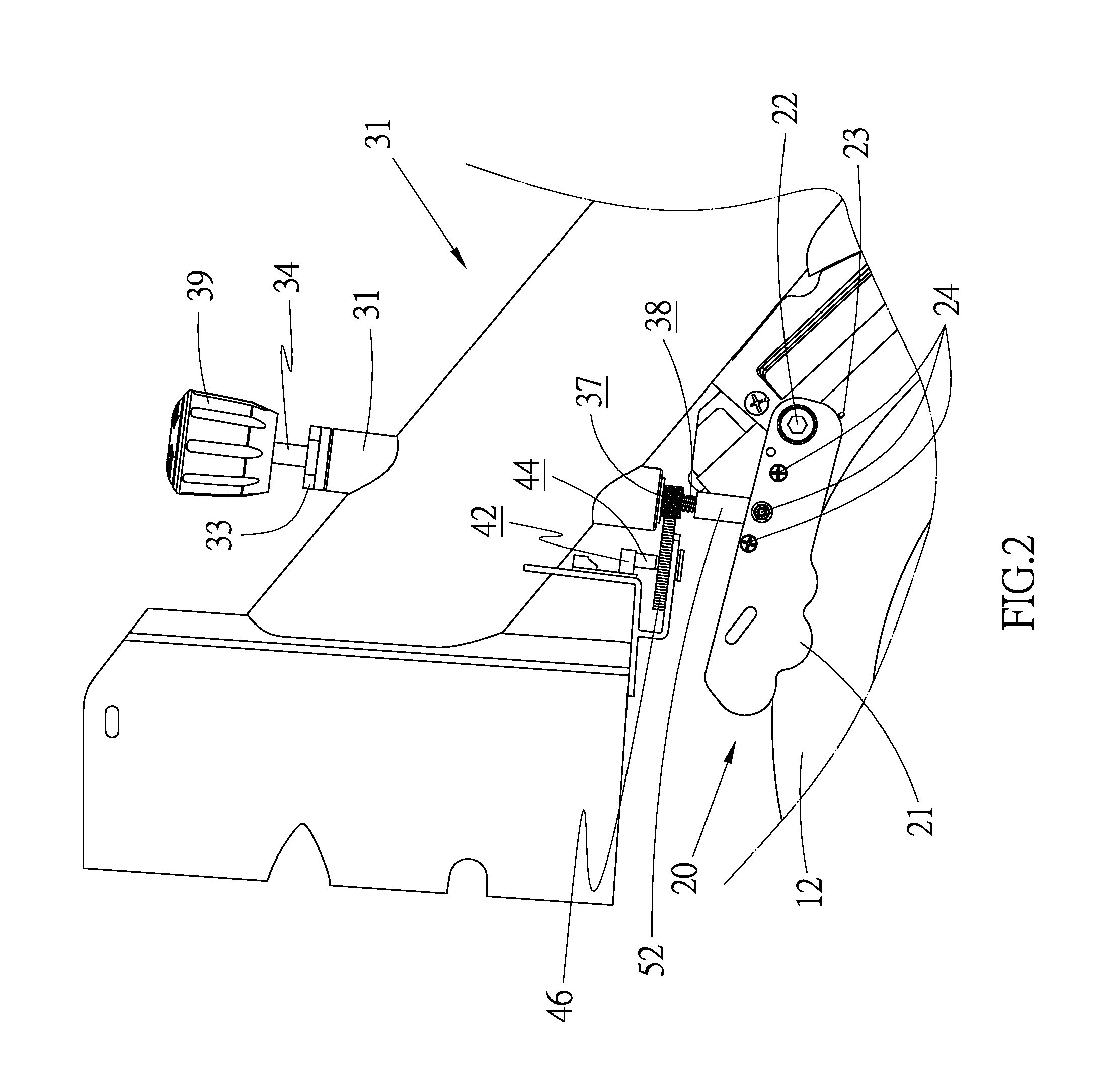
[0023]Referring to FIGS. 1 to 3, a spinning bike includes a frame 10, a flywheel 12, a resistance device 20, an adjustment assembly 30 and a sensor device 40 according to the preferred embodiment of the present invention. The flywheel 12 is connected to the frame 10. The flywheel 12 can be located in a front or rear portion of the frame 10. The flywheel 12 can spin. The magnetic resistance device 20 is connected to a portion of the frame 10 near the flywheel 12. The magnetic resistance device 20 is used to provide magnetic resistance against the spinning of the flywheel 12. The adjustment assembly 30 is operable to move the magnetic resistance device 20 relative to the flywheel 12. The sensor device 40 is used to measure the value of the magnetic resistance.

[0024]The magnetic resistance device 20 includes two lateral plates 21, a connector 22, a torque spring 23 and two groups of magnetic elements 26. The connector 22 is used to pivotally connect the lateral plates 21 to the frame 1...


PUM


Abstract

A spinning bike includes a frame, a flywheel connected to the frame, a magnetic resistance device for providing magnetic resistance against the flywheel, an adjustment assembly for moving the magnetic resistance device relative to the flywheel, and a sensor device for measuring the magnetic resistance. The adjustment assembly includes a rod extending throughout a tube. The tube is secured to the frame and includes a stop at an end and a cover at another end. The rod includes a pinion and a thread. The thread and a portion of the pinion extend beyond the stop of the tube. The sensor device includes an axle connected to a variable resistor and a gear. The gear is engaged with the portion of the pinion that extends out of the tube. The electric resistance of the variable resistor is changeable by rotating the axle and translated into the value of the magnetic resistance.

Description

BACKGROUND OF INVENTION[0001]1. Field of Invention[0002]The present invention relates to an exercise machine equipped with a sensor device and, more particularly, to a spinning bike equipped with a sensor device.[0003]2. Related Prior Art[0004]As disclosed in U.S. Pat. Nos. 5,145,480, 5,310,392, 5,324,242 and 6,569,063, an exercise machine can be equipped with a magnetic resistance device to adjustably increase resistance against a person who is working out on the exercise machine. A conventional magnetic resistance device includes a plurality of magnetic elements provided near a flywheel of a spinning bike for example. The magnetic elements are used to provide magnetic resistance against spinning of the flywheel.[0005]However, the conventional magnetic resistance device is not equipped with any sensor device to provide a user with the value of the magnetic resistance. A user has to depend on his or her feeling to adjust the magnetic resistance by feeling.[0006]As disclosed in U.S. ...

Claims


Application Information

Patent Timeline
IPC IPC(8): A63B22/06A63B23/04A63B24/00A63B21/00
CPCA63B22/0605A63B21/00076A63B21/00192A63B21/1465A63B2220/833A63B23/0476A63B24/0062A63B2022/0658A63B21/1496A63B71/0622A63B21/005A63B21/0051A63B21/015A63B21/225A63B24/0087A63B2071/0081A63B2071/065A63B2220/36A63B2220/58A63B21/00069
Inventor LO, CHIU HSIANG
Owner DK CITY CORP
Why Eureka
Try Eureka