
Formed material manufacturing method and surface treated metal plate used in same

a manufacturing method and technology of metal plates, applied in the direction of coatings, hollow objects, other domestic objects, etc., can solve the problems of deterioration of the performance of a product manufactured using the formed material, dents on the surface of the ironed formed portion, etc., to avoid large load on a part of the surface, and reduce the amount of generated powder form residue

Active Publication Date: 2016-10-27
NISSHIN STEEL CO LTD
View PDF1 Cites 0 Cited by
  • Summary
  • Abstract
  • Description
  • Claims
  • Application Information

AI Technical Summary

Benefits of technology

The formed material manufacturing method described in this patent ensures that the amount of ironing applied to the metal surface remains constant, by providing a clearance between the inner surface of the pushing hole and the outer surface of the punch. This prevents generation of a large load on a part of the surface and reduces the amount of powder form residue. Additionally, a surface treated metal plate with a surface treated layer and a lubricating film can be used to further reduce the amount of generated powder form residue regardless of processing conditions.

Problems solved by technology

The powder form residue causes problems such as formation of minute pockmarks (dents) in the surface of the ironed formed portion and deterioration of the performance of a product manufactured using the formed material.

Method used


Image

  • Formed material manufacturing method and surface treated metal plate used in same
  • Formed material manufacturing method and surface treated metal plate used in same
  • Formed material manufacturing method and surface treated metal plate used in same

Examples


first embodiment

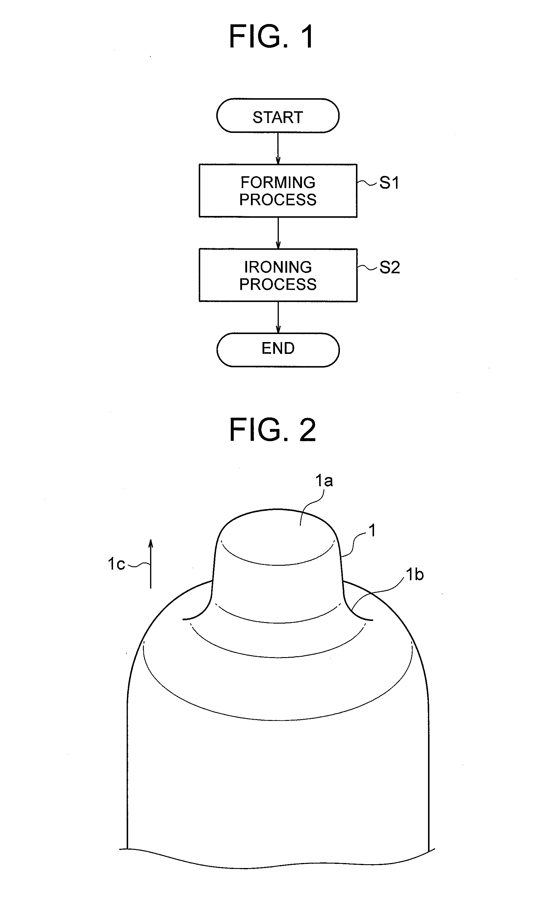
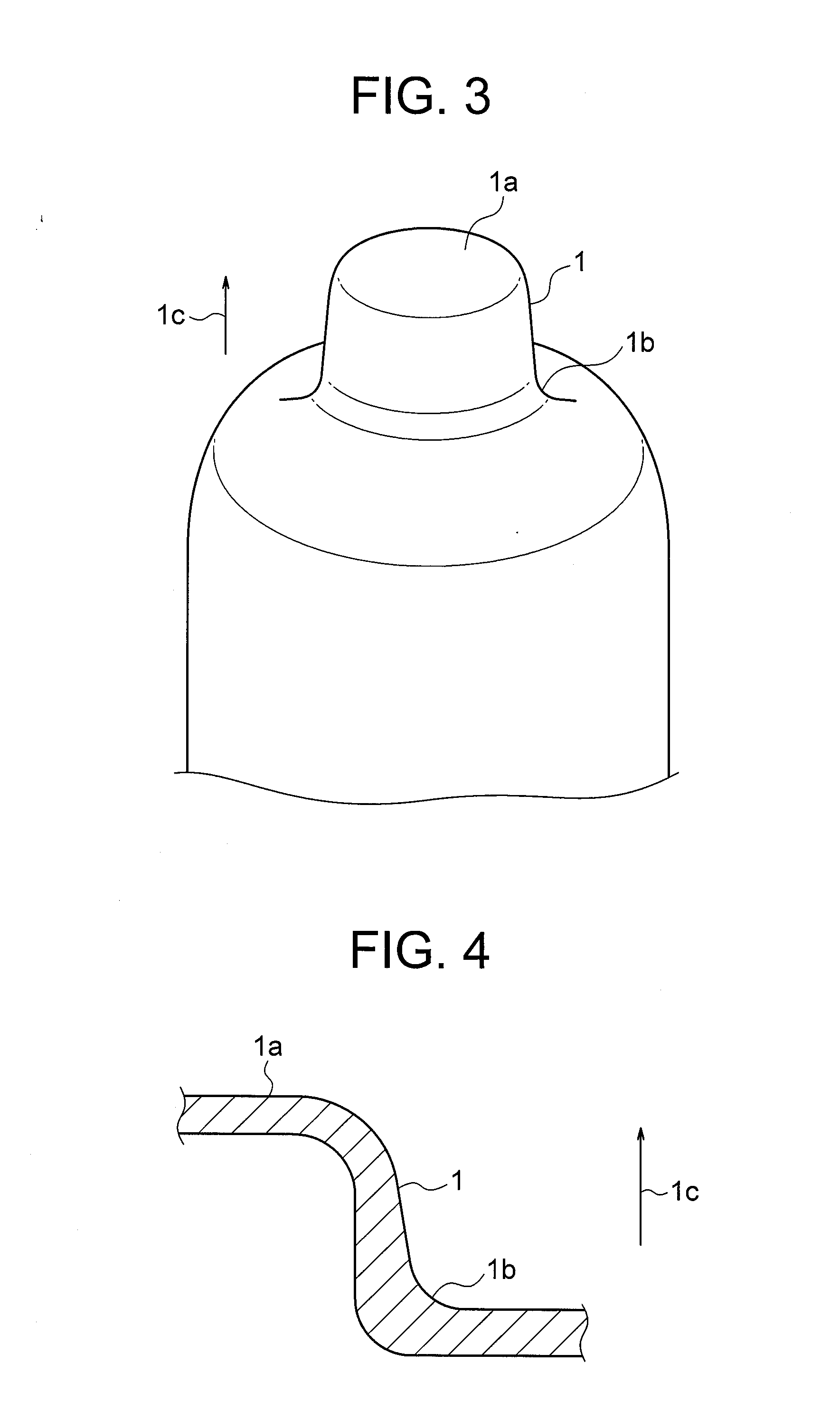
[0026]FIG. 1 is a flowchart showing a formed material manufacturing method according to an embodiment of the present invention. FIG. 2 is a perspective view showing a formed material including a formed portion 1 formed by a forming process S1 shown in FIG. 1. FIG. 3 is a perspective view showing the formed material including the formed portion 1 following an ironing process S2 shown in FIG. 1.

[0027]As shown in FIG. 1, the formed material manufacturing method according to this embodiment includes the forming process S1 and the ironing process S2. The forming process S1 is a process for forming the formed portion 1 (see FIG. 2) in a convex shape by performing at least one forming process on a surface treated metal plate. The forming process includes a pressing process such as drawing or stretching. The surface treated metal plate includes a surface treated layer provided on a surface of the metal plate, and a lubricating film provided on a surface of the surface treated layer. The sur...


PUM

PropertyMeasurementUnit
thicknessaaaaaaaaaa
thicknessaaaaaaaaaa
thicknessaaaaaaaaaa

Abstract

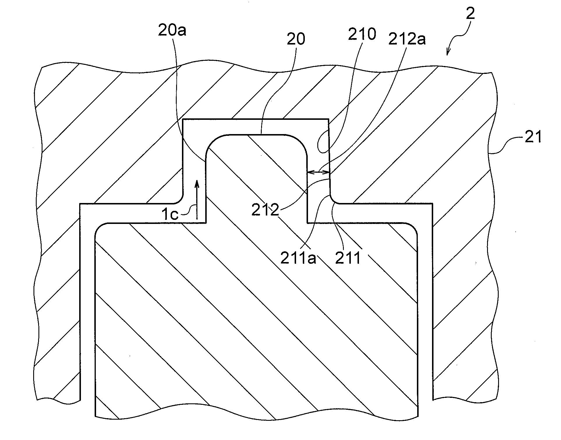
A formed material manufacturing method according to present invention includes the steps of forming a convex formed portion by performing at least one forming process on a surface treated metal plate, and performing ironing on the formed portion using an ironing mold after forming the formed portion. The ironing mold includes a punch that is inserted into the formed portion, and a die having a pushing hole into which the formed portion is pushed together with the punch. An inner peripheral surface of the pushing hole extends non-parallel to an outer peripheral surface of the punch, and the inner peripheral surface is provided with a clearance that corresponds to an uneven plate thickness distribution, in the pushing direction, of the formed portion prior to the ironing relative to the outer peripheral surface to ensure that an amount of ironing applied to the formed portion remains constant in the pushing direction.

Description

TECHNICAL FIELD[0001]Present invention relates to a formed material manufacturing method in which ironing is performed on a formed portion, and a surface treated metal plate used therein.BACKGROUND ART[0002]A convex formed portion is typically formed by performing a pushing process such as drawing using a surface treated metal plate such as a coated steel plate as a raw material. When the formed portion requires a particularly high degree of dimensional precision, ironing is implemented on the formed portion after the formed portion is formed. Ironing is a processing method of setting a clearance between a punch and a die to be narrower than a plate thickness of the formed portion prior to ironing, and then ironing a plate surface of the formed portion using the punch and the die so that the plate thickness of the formed portion matches the clearance between the punch and the die.[0003]A configuration disclosed in Patent Document 1 and so on, shown below, for example, may be employe...

Claims


Application Information

Patent Timeline
Patent Type & Authority Applications(United States)
IPC IPC(8): B21D22/28B21D51/10
CPCB21D22/286C23C2/06B21D51/10B21D22/28
Inventor NAKAMURA, NAOFUMIYAMAMOTO, YUDAIKUROBE, JUN
Owner NISSHIN STEEL CO LTD
Learn More