Eureka AIR delivers breakthrough ideas for toughest innovation challenges, trusted by R&D personnel around the world.

Pushing device, moving mechanism and aircraft

Active Publication Date: 2016-10-27
AIRBUS BEIJING ENG CENT
View PDF0 Cites 1 Cited by
  • Summary
  • Abstract
  • Description
  • Claims
  • Application Information

AI Technical Summary

Benefits of technology

The present patent aims to provide a pushing device that can protect the moving mechanism of an aircraft from faults. It suggests using a catapult device in the damping device of the moving mechanism that can be installed easily and without causing significant changes to the existing structures of the airplane. This makes the manufacture and installation of the catapult device easier and more flexible.

Problems solved by technology

The damping device moves along with the movement of the moving component, and therefore has a possibility of breaking.
Once the damping device breaks, it is possible that the broken part in the damping device impacts a stationary structure, for installing the moving component (for example, a framework structure of a wing), of the airplane and cause damage of the stationary structure which is difficult to repair.
In addition, it is possible to further cause a jam after the broken part in the damping device impacts the stationary structure, thereby causing that the moving component fails to keep moving and working normally to achieve its intended function, or, two broken parts in the damping device interfere with each other, thereby leading to a jam and thus causing that the moving component fails to keep moving and working normally to achieve its intended function as well.
Thus, damage of the rib 300A (the rib 300A is generally difficult to repair) is caused, and it is possible to further cause a jam, thereby resulting in that the moving component fails to keep moving or fails to keep moving smoothly (for example, fails to retract or retract smoothly along the direction A shown in FIG. 1).

Method used


Image

  • Pushing device, moving mechanism and aircraft
  • Pushing device, moving mechanism and aircraft
  • Pushing device, moving mechanism and aircraft

Examples


Embodiment Construction

[0032]The present application is described in detail hereinafter with reference to the accompanying drawings and by means of the exemplary embodiment. The following detailed description of the present application is only for the purpose of illustration rather than limitation to the present application and the applications or usages thereof.

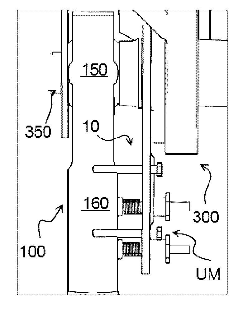
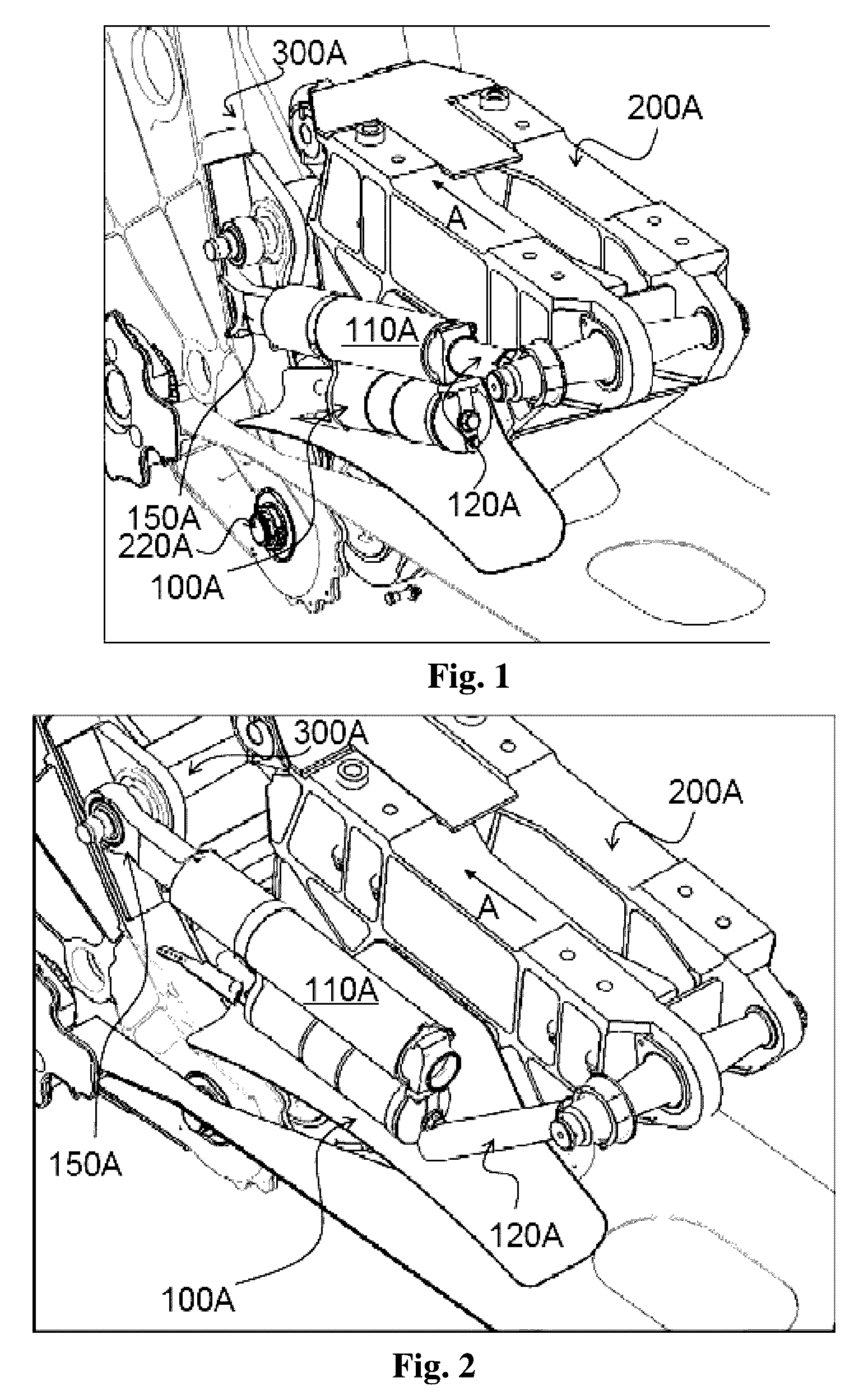
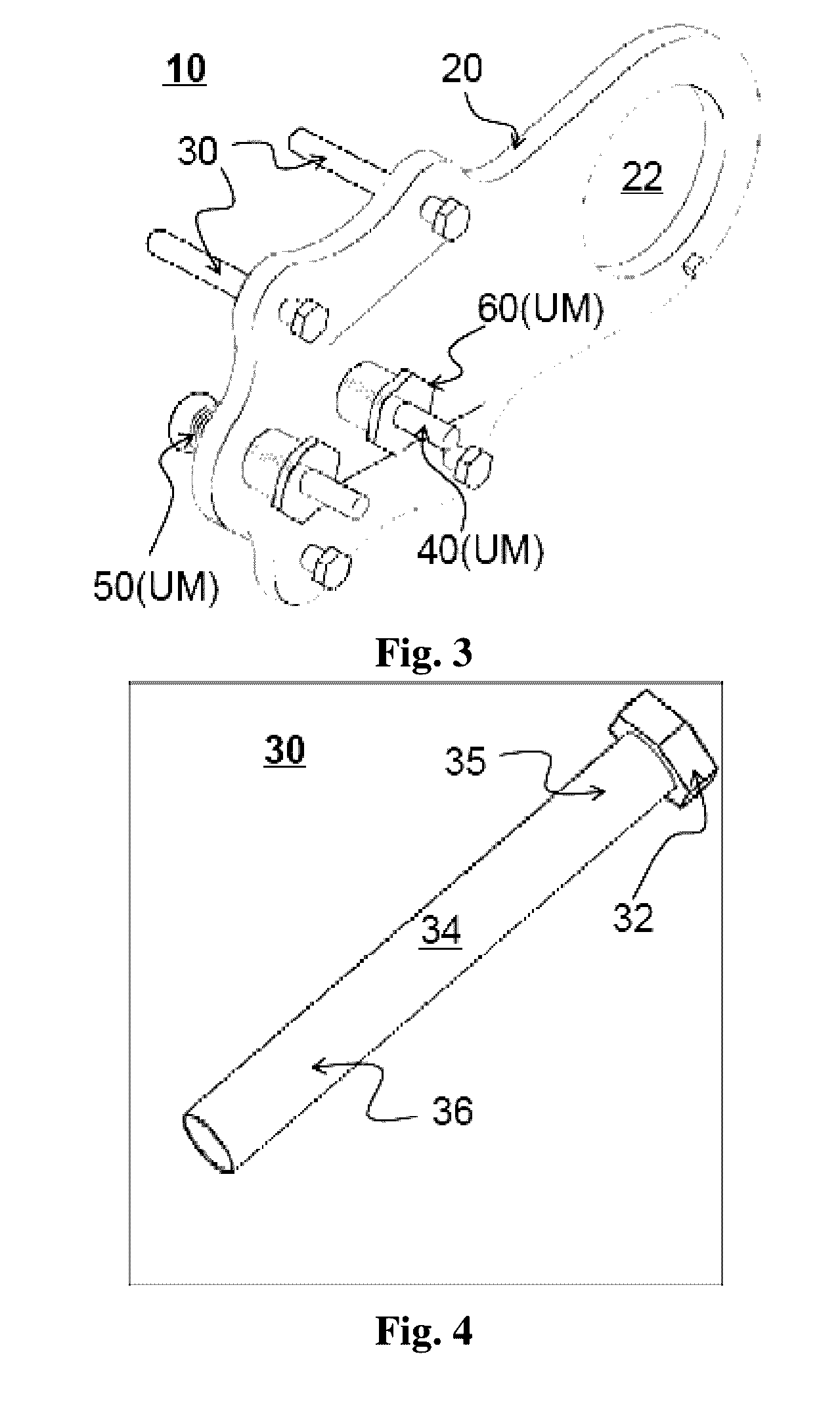
[0033]First, a catapult device 10 according to an exemplary embodiment of the present application is described with reference to FIGS. 3 to 10. FIG. 3 is a perspective view showing a catapult device according to an exemplary embodiment of the present application; FIGS. 4 to 8 are respectively perspective views showing constituent components of the catapult device according to an exemplary embodiment of the present application; FIG. 9 is a schematic view for illustrating the installation of the catapult device according to an exemplary embodiment of the present application; and FIG. 10 is an elevation view showing the catapult device having been in...


PUM


Abstract

The present application relates to a pushing device, a moving mechanism and an aircraft. According to an aspect of the present application, a pushing device for a moving mechanism of an aircraft is provided, the moving mechanism including a primary moving device and an auxiliary moving device assisting the primary moving device, the pushing device including a support member and a pushing assembly supported by the support member, and the pushing assembly including a pushing element and an energy storage element. The pushing element is adapted to push a broken part of the auxiliary moving device to an offset position from a normal working position by means of energy from the energy storage element when the auxiliary moving device breaks. According to the present application, it is possible to provide an effective fault protection to the moving mechanism of the aircraft.

Description

[0001]This application claims priority to Chinese Patent Application No. 201510200853.4, titled “PUSHING DEVICE, MOVING MECHANISM AND AIRCRAFT”, filed with the Chinese State Intellectual Property Office on Apr. 24, 2015, which is incorporated by reference in its entirety herein.FIELD OF THE INVENTION[0002]This application relates to a pushing device, a moving mechanism including the pushing device and an aircraft including the moving mechanism, and in particular to a pushing device which is capable of providing an effective fault protection to a moving mechanism of an aircraft and is used in the moving mechanism of the aircraft.BACKGROUND OF THE INVENTION[0003]In an aircraft, such as an airplane, a variety of different moving components are provided for achieving respective functions. For example, these moving components are various moving airfoils arranged on wings, such as flaps for obtaining a larger lift and a better maneuvering capability at a low speed (the flaps may be classi...

Claims


Application Information

Patent Timeline
IPC IPC(8): B64C13/28F03G1/10B64C9/14
CPCB64C13/28B64C2009/143F03G1/10B64C9/14B64C9/16B64C13/00B64C13/341
Inventor LI, MINGSUN, YUMIN
Owner AIRBUS BEIJING ENG CENT
Why Eureka
Eureka Blog
Learn More