Apparatus and method for controlling implant process

a technology of ion implantation and process, applied in the direction of vacuum evaporation coating, electric discharge tube, coating, etc., can solve the problems of limiting the ability to apply a targeted waveform to the substrate, unable to control non-uniform implantation, and non-uniform implantation

Active Publication Date: 2016-10-27
VARIAN SEMICON EQUIP ASSOC INC
View PDF10 Cites 5 Cited by
  • Summary
  • Abstract
  • Description
  • Claims
  • Application Information

AI Technical Summary

Benefits of technology

[0009]In another embodiment, an apparatus to control an implant process may include: a beam scanner to apply, during a non-uniform scanning mode, a plurality of different waveforms to generate a scan of an ion beam along a scan direction, wherein a given waveform of the plurality of different waveforms comprises a plurality of scan segments, wherein a first scan segment comprises a first scan rate and a second scan segment comprises a second scan rate different from the first scan rate; a scan adjustment component coupled to the beam scanner; and at least one computer readable medium comprising instructions, where the instructions, when executed, cause the scan adjustment component to: receive a beam width for the ion beam along the scan direction; receive a selection for a scanning mode to apply for the beam scanner; and determine a plurality of current ratios based on a measured integrated current of the ion beam for at least two different waveforms of the plurality of different waveforms when the selection is a non-uniform scanning mode and a threshold is exceeded.

Problems solved by technology

While previous development focused on improving the uniformity of wafer processing, many present-day customers of ion implantation apparatus may request various patterns of non-uniform process control for Precision Materials Engineering (PME).
In particular methods, non-uniform implantation may be performed by scanning a spot beam according to a predetermined waveform in order to provide variable ion doses to different regions of a substrate.
A limitation of the aforementioned targeted non-uniform ion implantation lies in the ability to control non-uniform implantation when the spot beam exceeds a certain size.
This overlap may limit the ability to apply a targeted waveform to the substrate to generate a targeted non-uniform implantation and at the same time accurately measure ion dose provided to the substrate.

Method used


Image

  • Apparatus and method for controlling implant process
  • Apparatus and method for controlling implant process
  • Apparatus and method for controlling implant process

Examples


Embodiment Construction

[0015]The present embodiments will now be described more fully hereinafter with reference to the accompanying drawings, where some embodiments are shown. The subject matter of the present disclosure may be embodied in many different forms and are not to be construed as limited to the embodiments set forth herein. Instead, these embodiments are provided so this disclosure will be thorough and complete, and will fully convey the scope of the subject matter to those skilled in the art. In the drawings, like numbers refer to like elements throughout.

[0016]The embodiments described herein provide novel processing apparatus and methods to generate controlled ion implantation of substrates.

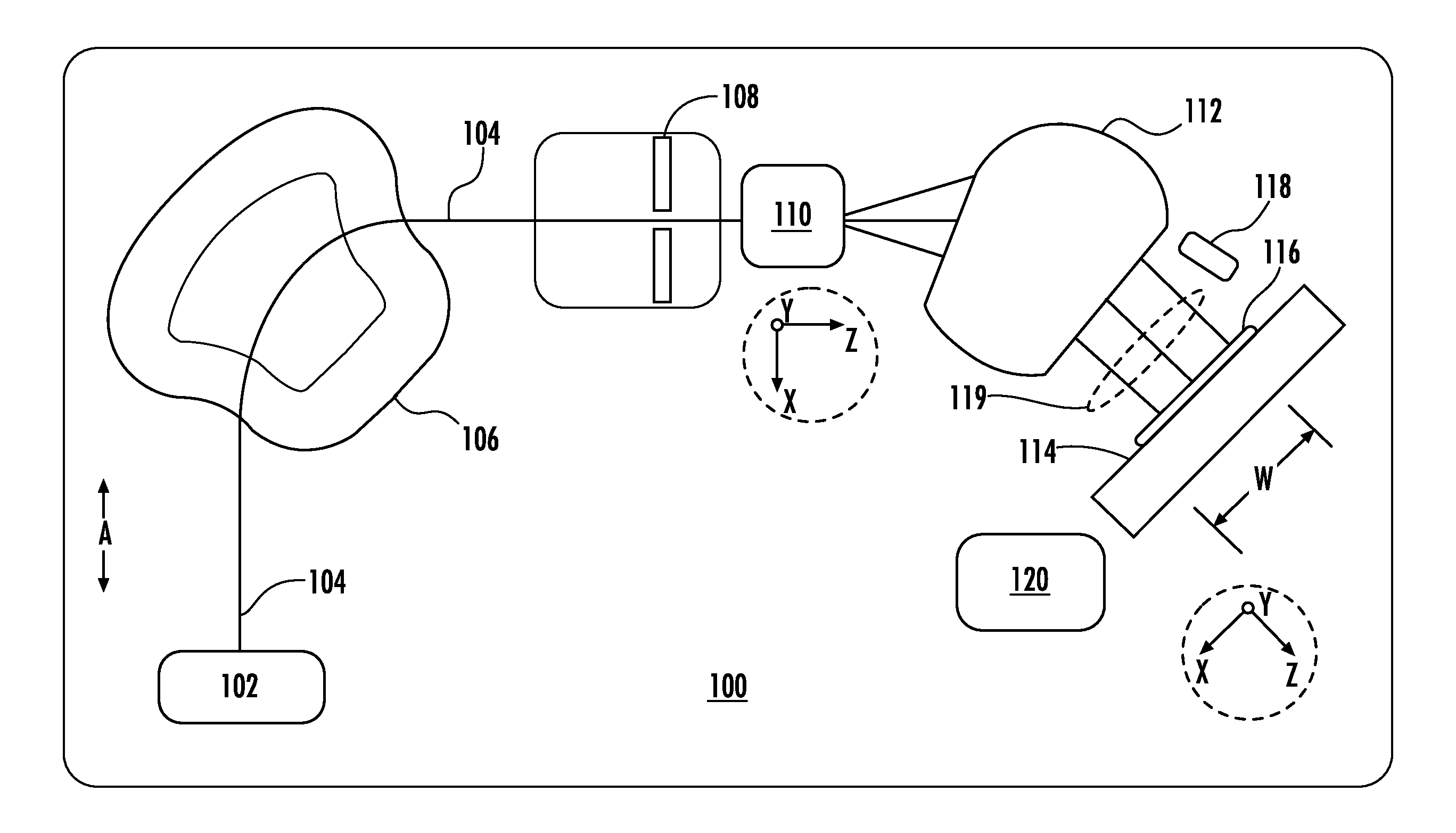
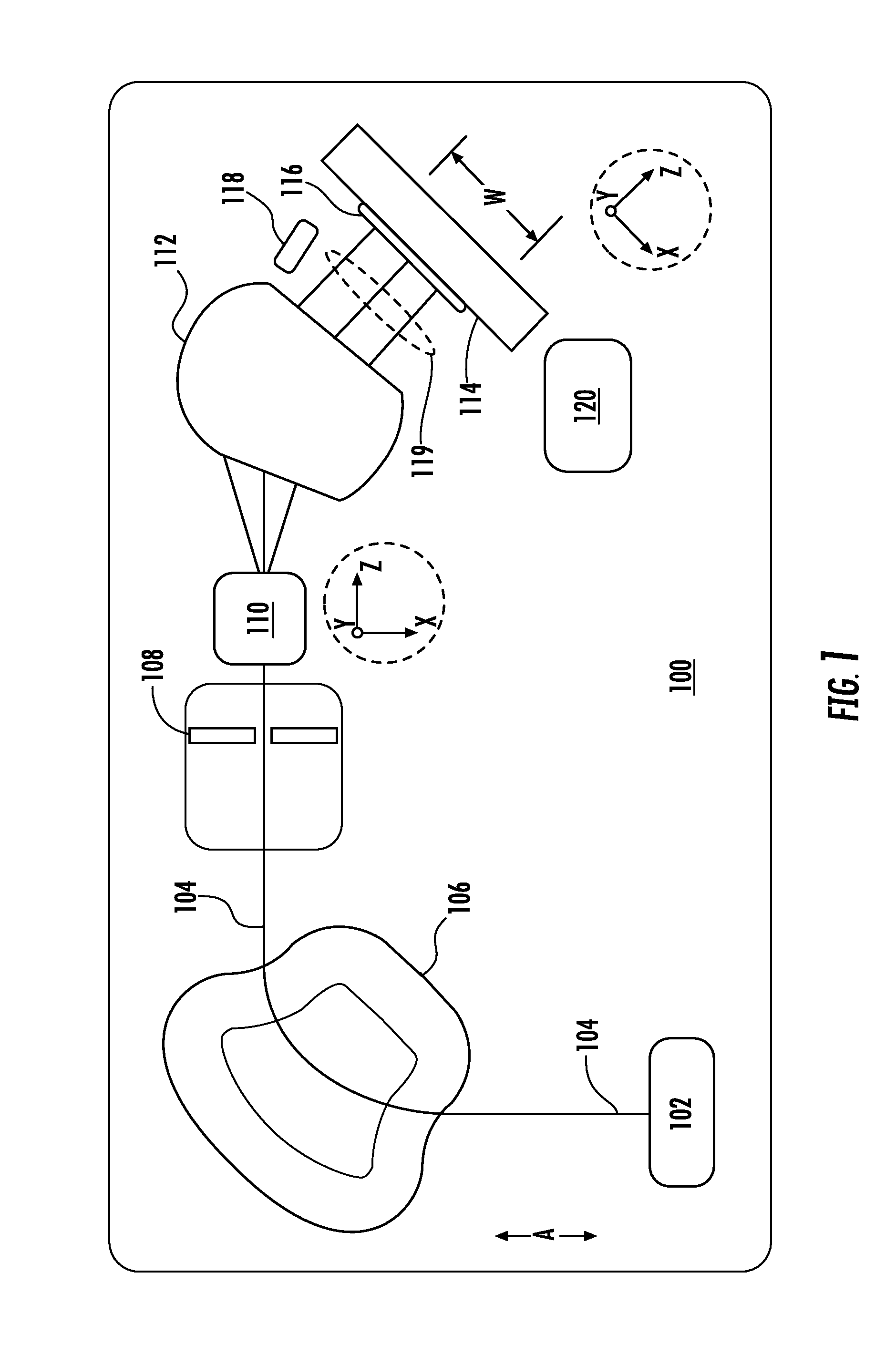
[0017]FIG. 1 depicts a top plan view in block form of a beamline ion implanter, shown as the ion implanter 100, in accordance with various embodiments of the disclosure. The ion implanter 100 includes an ion source 102 configured to generate an ion beam 104. The ion beam 104 may be provided as a spot bea...


PUM

PropertyMeasurementUnit
energyaaaaaaaaaa
voltageaaaaaaaaaa
half widthaaaaaaaaaa

Abstract

An apparatus includes a beam scanner applying, during a non-uniform scanning mode, a plurality of different waveforms generating a scan of an ion beam along a scan direction, wherein a given waveform comprises a plurality of scan segments, wherein a first scan segment comprises a first scan rate and a second scan segment comprises a second scan rate different from the first scan rate; a current detector intercepting the ion beam outside of a substrate region and recording a measured integrated current of the ion beam for a given waveform; and a scan adjustment component coupled to the beam scanner and comprising logic to determine: when a beam width of the ion beam along the scan direction exceeds a threshold; and a plurality of current ratios based on the measured integrated current of the ion beam for at least two different waveforms of the plurality of waveforms.

Description

[0001]This application claims priority to U.S. provisional patent application No. 62 / 151,539, filed Apr. 23, 2015 and incorporated by reference herein in its entirety.FIELD[0002]The present embodiments relate to processing apparatus and methods, and more particularly, to components and methods to control processing in ion implantation processes.BACKGROUND[0003]In the present day, various types of processing apparatus are employed to treat or process substrates with ions. For processing substrates such as semiconductor substrates, ions may be used to etch layers or features on a substrate. Ions may also be used to deposit a layer or structures on a substrate, to implant a species into a substrate, or to amorphize a substrate. Techniques have also been developed to monitor processing of a substrate in order to control the processing of a substrate. In the present day, ion implantation tools provide increasing versatility for implantation of a substrate or wafer. While previous develop...

Claims


Application Information

Patent Timeline
Patent Type & Authority Applications(United States)
IPC IPC(8): C23C14/48H01J37/317H01J37/08
CPCC23C14/48H01J37/3171H01J37/08C23C14/54H01J2237/31703H01J2237/24542H01J37/304H01J2237/24535H01J2237/30483H01J2237/31701
Inventor GAMMEL, GEORGE M.EVANS, MORGAN D.TODOROV, STANISLAV S.HUSSEY, NORMAN E.GIBILARO, GREGORY R.
Owner VARIAN SEMICON EQUIP ASSOC INC
Why Eureka
Try Eureka