Plasma processing methods and apparatus

a processing method and apparatus technology, applied in the field of materials processing, can solve the problems of non-uniform processing, difficult to achieve precise control of angular velocity, and stress that may damage the substrate, so as to facilitate the uniform processing of target surfaces, facilitate precise control of the movement of articles, and reduce acceleration of articles

Inactive Publication Date: 2007-02-20
INVENSAS CORP
View PDF45 Cites 3 Cited by
  • Summary
  • Abstract
  • Description
  • Claims
  • Application Information

AI Technical Summary

Benefits of technology

[0008]Some embodiments of the present invention provide methods and apparatus for moving the target articles relative to the plasma so as to facilitate uniform processing of the target surfaces. In particular, some embodiments

Problems solved by technology

Since the substrate points that are located farther from the rotation axis move faster than the points closer to the rotation axis, the points farther from the rotation axis could be exposed to the plasma for less time than the points closer to the axis, resulting in non-uniform processing.
Thus, varying the angular velocity of the substrate leads to accelerations that make precise control of the angular velocity more difficult to achieve.
Further, these accelerations create stresses that may damage the substra

Method used


Image

  • Plasma processing methods and apparatus
  • Plasma processing methods and apparatus
  • Plasma processing methods and apparatus

Examples


Embodiment Construction

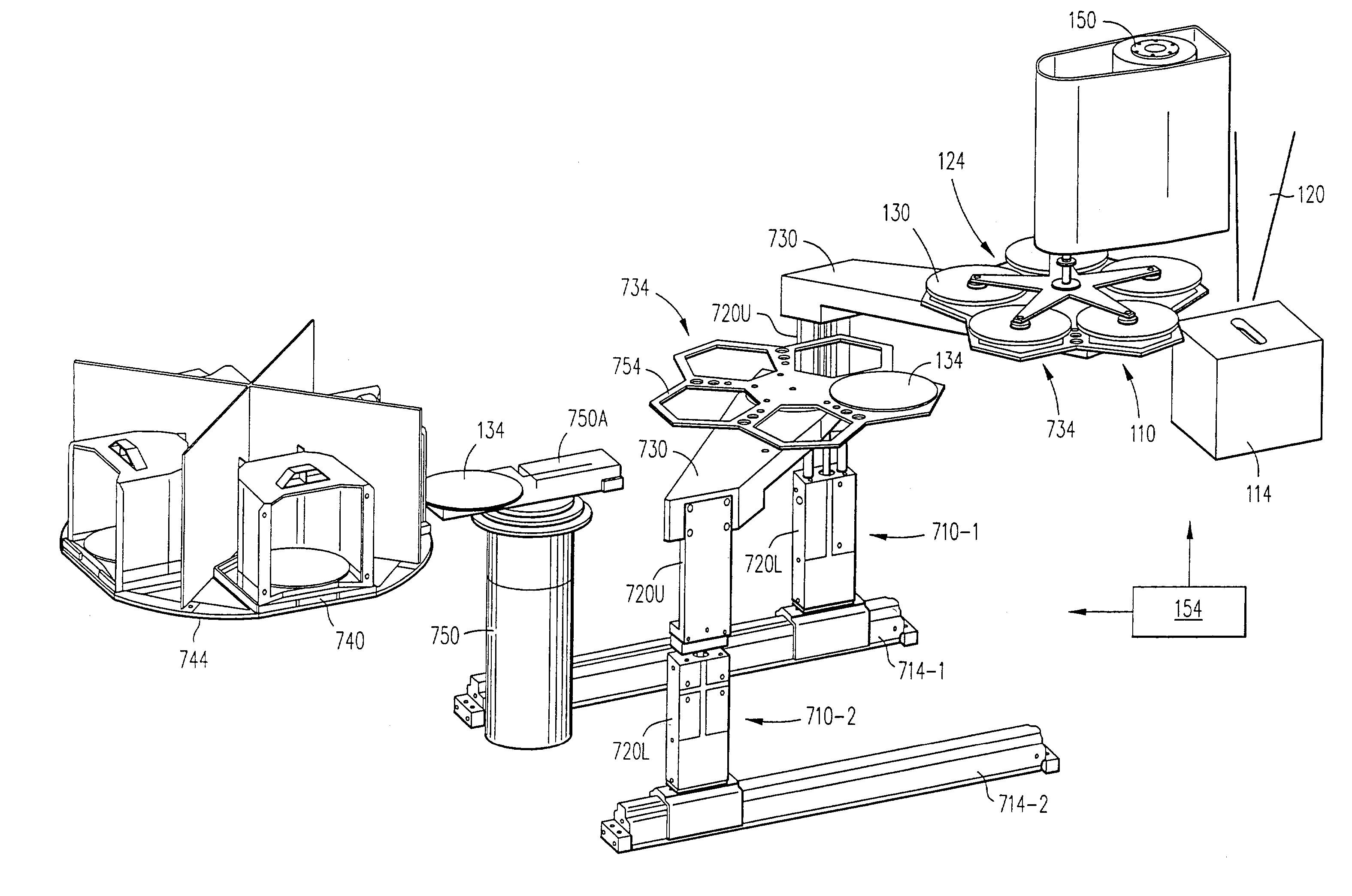
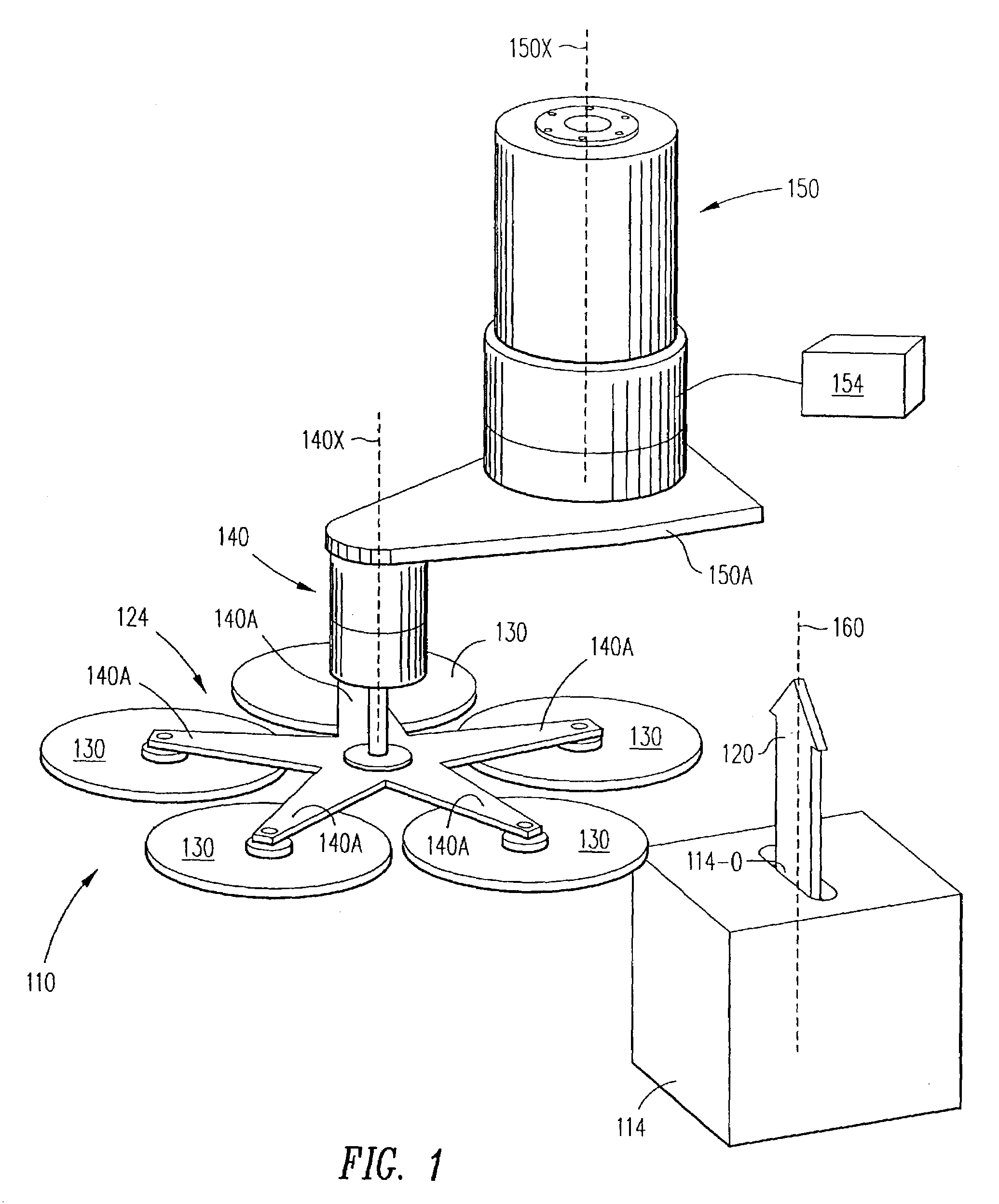
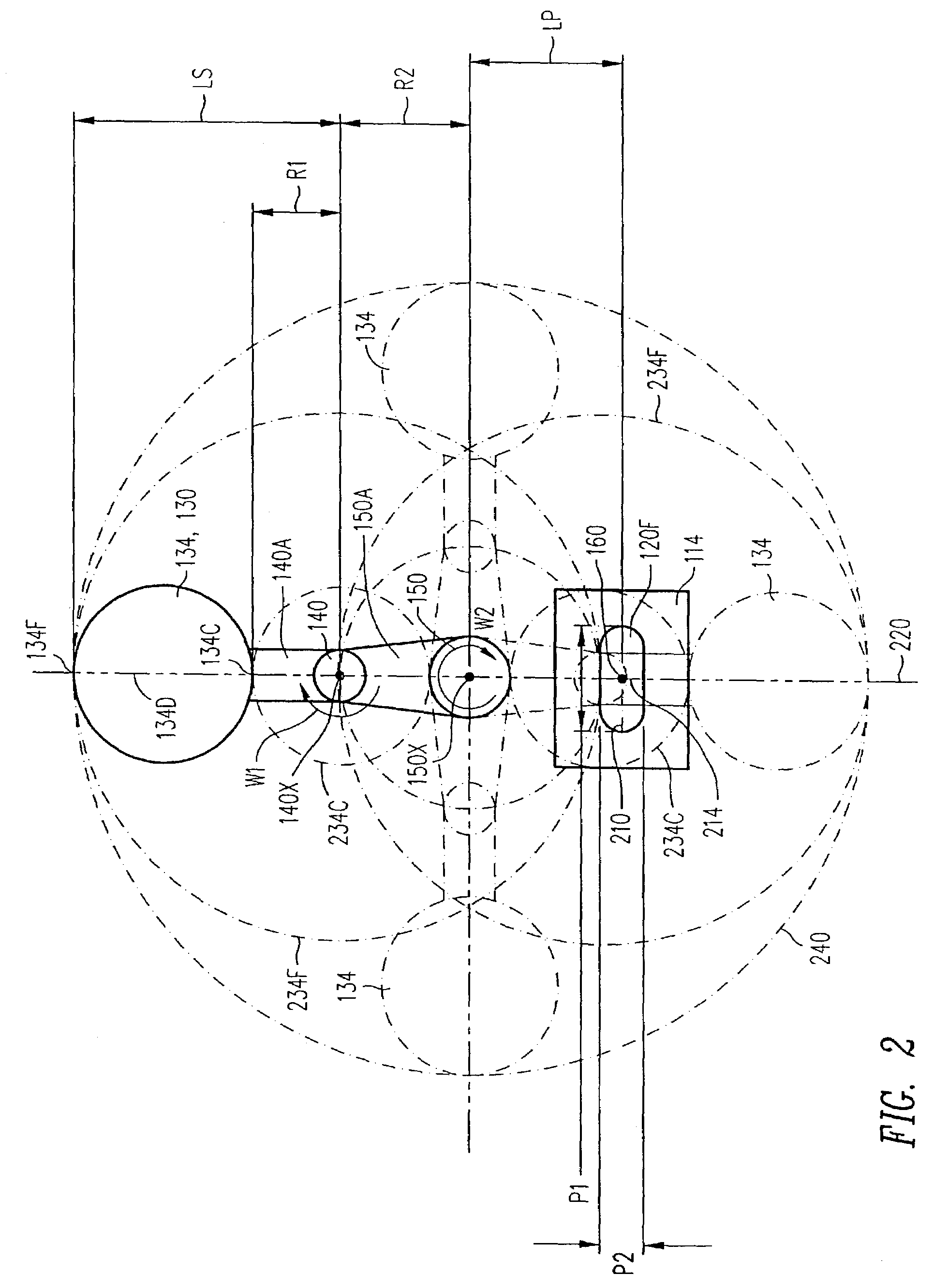
[0025]In plasma processing system 110 (FIG. 1) plasma source 114 generates plasma jet 120 schematically shown by an arrow. Plasma jet 120 flows vertically upwards through an elongated opening 114-O in source 114. The opening 114-O is elliptical in some embodiments. Horizontal cross sections of plasma jet 120 are also elliptical. In some embodiments, the opening 114-O and the plasma horizontal cross sections have a shape of an elongated rectangle, perhaps with rounded corners.

[0026]Carrrousel 124 includes five holders 130. Each holder 130 holds an article 134 (FIG. 2) whose bottom surface is processed by plasma jet 120. Articles 134 in FIGS. 1–5 are round semiconductor wafers whose flat horizontal bottom surfaces are processed with plasma 120. In some embodiments, the articles are not round and / or are not semiconductor articles. In some semiconductor-wafer embodiments, holders 130 are non-contact wafer holders such as described, for example, in PCT publication WO 96 / 21943 “Device For...


PUM

PropertyMeasurementUnit
Timeaaaaaaaaaa
Pressureaaaaaaaaaa
Distanceaaaaaaaaaa

Abstract

To move an article in and out of plasma during plasma processing, the article is rotated by a first drive around a first axis, and the first drive is itself rotated by a second drive. As a result, the article enters the plasma at different angles for different positions of the first axis. The plasma cross-section at the level at which the plasma contacts the article is asymmetric so that those points on the article that move at a greater linear velocity (due to being farther from the first axis) move longer distances through the plasma. As a result, the plasma processing time becomes more uniform for different points on the article surface. In some embodiments, two shuttles are provided for loading and unloading the plasma processing system. One of the shuttles stands empty waiting to unload the processed articles from the system, while the other shuttle holds unprocessed articles waiting to load them into the system. After the plasma processing terminates, the empty shuttle unloads processed articles from the system, takes the articles away, and gets unloaded and reloaded with unprocessed articles. Meanwhile, the other shuttle loads unprocessed articles into the system and the plasma processing begins. Since the plasma processing system does not wait for the first shuttle, the productivity of the system is increased.

Description

CROSS-REFERENCE TO RELATED APPLICATIONS[0001]The present application is a division of U.S. patent application Ser. No. 09 / 542,519, filed Apr. 3, 2000 now U.S. Pat. No. 6,627,039, incorporated herein by reference, which is a division of U.S. patent application Ser. No. 08 / 975,403, filed Nov. 20, 1997, now U.S. Pat. No. 6,139,678, incorporated herein by reference.STATEMENT REGARDING FEDERALLY SPONSORED RESEARCH[0002]Not Applicable.BACKGROUND OF THE INVENTION[0003]The present invention relates to processing of materials, and more particularly to plasma processing.[0004]Plasma processing is widely used to modify surface properties of materials. Thus, plasma is used in fabrication of integrated circuits to perform deposition, etch, cleaning, and rapid thermal anneal. Plasma-based surface processes are also used for hardening of surgical instruments and machine tools, and are used in aerospace, automotive, steel, biomedical, and toxic waste management industries. See, for example, M. A. L...

Claims


Application Information

Patent Timeline
IPC IPC(8): C23C16/00B65H1/00C23C16/453C23F1/00H01L21/302C23C16/458C23C16/513C23C16/54H01L21/00H01L21/205H01L21/3065H01L21/677H01L21/687H05H1/46
CPCC23C16/4584C23C16/513C23C16/54H01J37/32743H01J37/32788H01L21/68707H01L21/67017H01L21/67745H01L21/67796H01J2237/31701H01J2237/20228H01J37/32
Inventor SINIAGUINE, OLEG
Owner INVENSAS CORP
Why Eureka
Try Eureka