
Solar heating for site located oil storage or separation

a technology for oil storage or separation, which is applied in the direction of lighting and heating apparatus, separation processes, greenhouse gas reduction, etc., to achieve the effect of preventing waste and increasing the efficiency of oil and gas separator recovery

Inactive Publication Date: 2016-10-27
IND SOLAR HEATING SYST LLC
View PDF6 Cites 8 Cited by
  • Summary
  • Abstract
  • Description
  • Claims
  • Application Information

AI Technical Summary

Benefits of technology

The patent describes a system that uses safe, "green" solar heat to increase the temperature of oil and gas before or after it goes into a gas-fired separator. This system helps to reduce emissions into the atmosphere and the use of natural gas. It also reduces vapor generation in the separator by reducing the use of fire tubes.

Problems solved by technology

The buffer tank is large enough to store heat in the secondary fluid in times when the primary circuit does not provide sufficient heat (prolonged periods of cloudiness, for example).

Method used


Image

  • Solar heating for site located oil storage or separation
  • Solar heating for site located oil storage or separation
  • Solar heating for site located oil storage or separation

Examples


Embodiment Construction

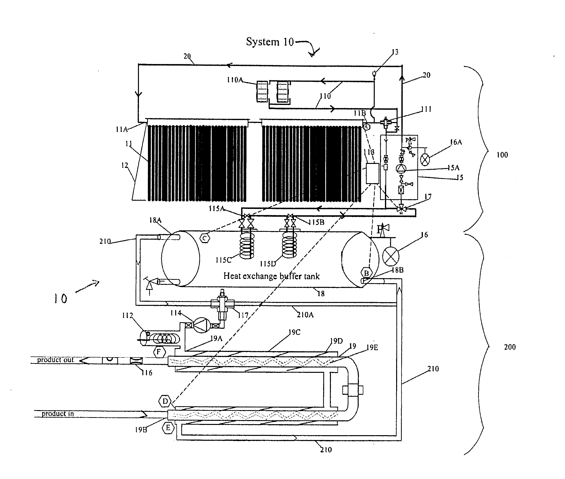
[0051]Turning to FIG. 5, an enhanced separator system 10 is provided for preventing waste. The system 10 in one embodiment includes an oil heat exchanger 19 having an oil bearing inner tube IT for use in conjunction with an existing, typically prior art separator.

[0052]A primary heating circuit 100 is disclosed. The primary heating circuit 100 includes a solar collector 11 (having one or more panels) mounted on a solar collector frame 12. A primary or first fluid FF (such as water, a synthetic heat transfer fluid, such as Syntherm A-32 or glycol) in the primary heating circuit 100 receives radiant heat from the sun at the solar collector 11. The solar collector 11 has an inlet 11A and an outlet 11B. A heating coil means, which may be a solar heat exchanger 115C / 115D, transfer heat from the first fluid FF to the second fluid SF found in buffer tank 18. Remote heating coil means 115C / 115D is immersed in a heat exchange buffer tank 18, which contains a secondary or second fluid SF, for...


PUM


Abstract

A system for providing supplemental or auxiliary heat to a crude oil separator is provided. The system includes a primary circuit carrying a fluid heated by a solar panel and a secondary circuit carrying a fluid heated by heat exchangers engaged with the primary circuit. The secondary circuit includes heat exchangers engaging the separator to provide auxiliary heat. The system may also include a source of off-grid electrical energy, such as a wind turbine and / or photoelectric cell.

Description

[0001]This continuation-in-part application claims priority from and the benefit of U.S. application Ser. No. 13 / 775,899, filed Feb. 25, 2013, which is a CIP of and claims priority and the benefit of U.S. application Ser. No. 13 / 325,743, filed Dec. 14, 2013, which claims prior to and benefit of U.S. Provisional Patent Application Ser. No. 61 / 602,305, filed Feb. 23, 2012, and U.S. Provisional Patent Application Ser. No. 61 / 423,367 filed Dec. 15, 2010; and incorporates the same by reference herein.FIELD OF THE INVENTION[0002]Solar energy to enhance oil and gas site location separator recovery and reduce pollution emission from conventional natural gas powered separators.BACKGROUND OF THE INVENTION[0003]This application incorporates by reference U.S. patent application Ser. No. 13 / 325,743, filed Dec. 14, 2011, entitled “Clean Solar Energy to Enhance Oil and Gas Location Separator Recovery.”[0004]Product coming out of the ground typically contains oil, but the oil is part of an emulsifi...

Claims


Application Information

Patent Timeline
Patent Type & Authority Applications(United States)
IPC IPC(8): F24J2/00F24J2/42F24S90/00
CPCF24J2/42F24J2/0023B01D17/042F24H1/208F24S10/45F24S20/40F24S30/422F24S30/425F24S40/55F24S90/00F24S90/10F28D1/0213F28D7/026F28D7/06F28D7/106F28D20/0034F28D20/0052F28D20/0056F28D2021/0059F28F27/02Y02E10/44Y02E10/47Y02E60/14Y02E70/30
Inventor BRUCE, WALLACECHACON, RICHARDRAY, MARK
Owner IND SOLAR HEATING SYST LLC
Learn More