Motor operated valve apparatus and motor operated valve controller

a technology of motor operated valves and controllers, which is applied in the direction of dynamo-electric converter control, operating means/release devices of valves, lighting and heating apparatus, etc., can solve the problem that the control cannot be started easily, and achieve the effect of accurate setting, highly efficient and accurate control

Active Publication Date: 2016-10-27
TGK
View PDF11 Cites 16 Cited by
  • Summary
  • Abstract
  • Description
  • Claims
  • Application Information

AI Technical Summary

Benefits of technology

[0016]According to this embodiment, the load on the motor is detected from the drive pulse when the motor is driven in the valve closing direction, and the valve switching point is set on the basis of the load. Specifically, the valve switching point is detected on the basis of a change in the motor loa

Problems solved by technology

Furthermore, since a method using feedback of the outlet temperature is employed, it requires time until the change in the temperature is detected, and control cannot be started readily after activation of the motor operated valve.
Such problems

Method used


Image

  • Motor operated valve apparatus and motor operated valve controller
  • Motor operated valve apparatus and motor operated valve controller
  • Motor operated valve apparatus and motor operated valve controller

Examples


Embodiment Construction

[0021]The invention will now be described by reference to the preferred embodiments. This does not intend to limit the scope of the present invention, but to exemplify the invention.

[0022]An embodiment of the present invention will now be described in detail with reference to the accompanying drawings. In the following description, for convenience of description, the positional relationship in each structure may be expressed with reference to how each structure is depicted in the drawings.

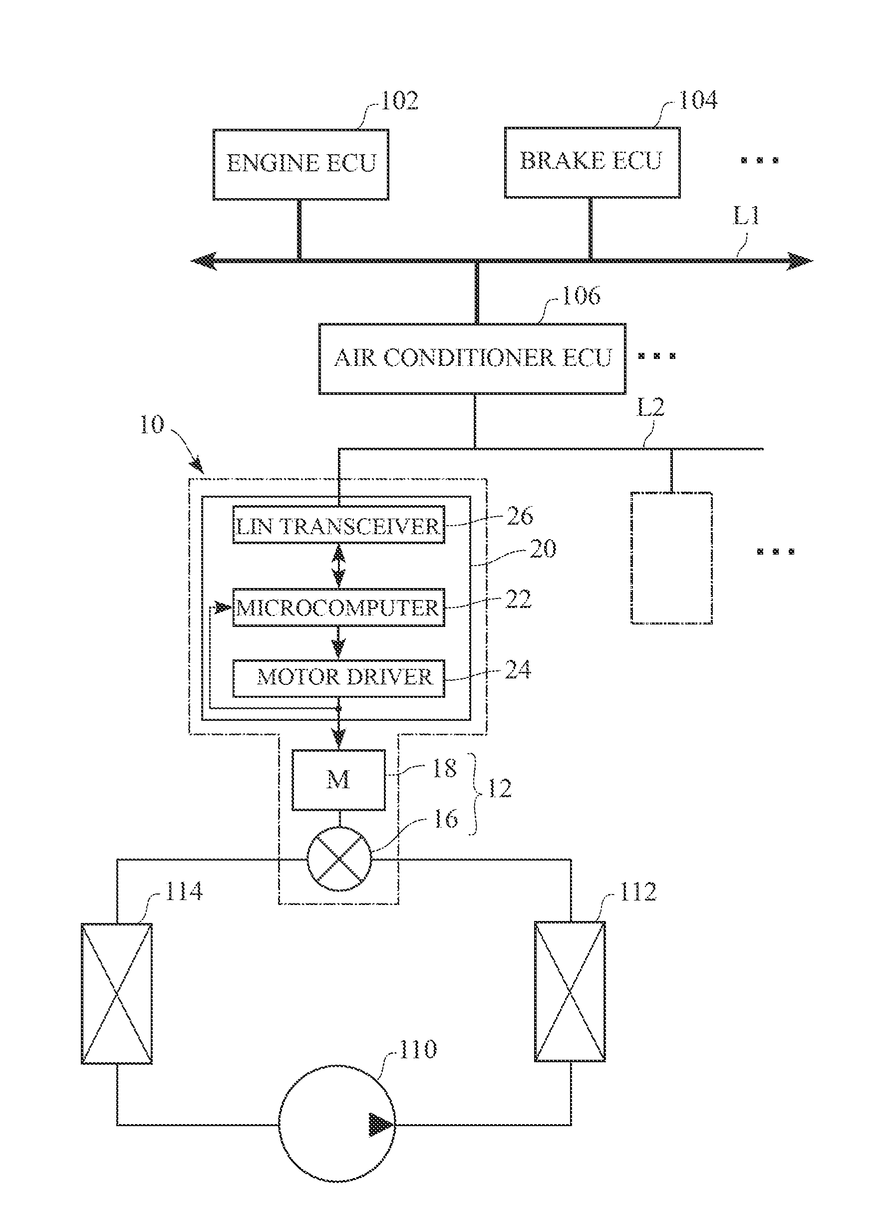
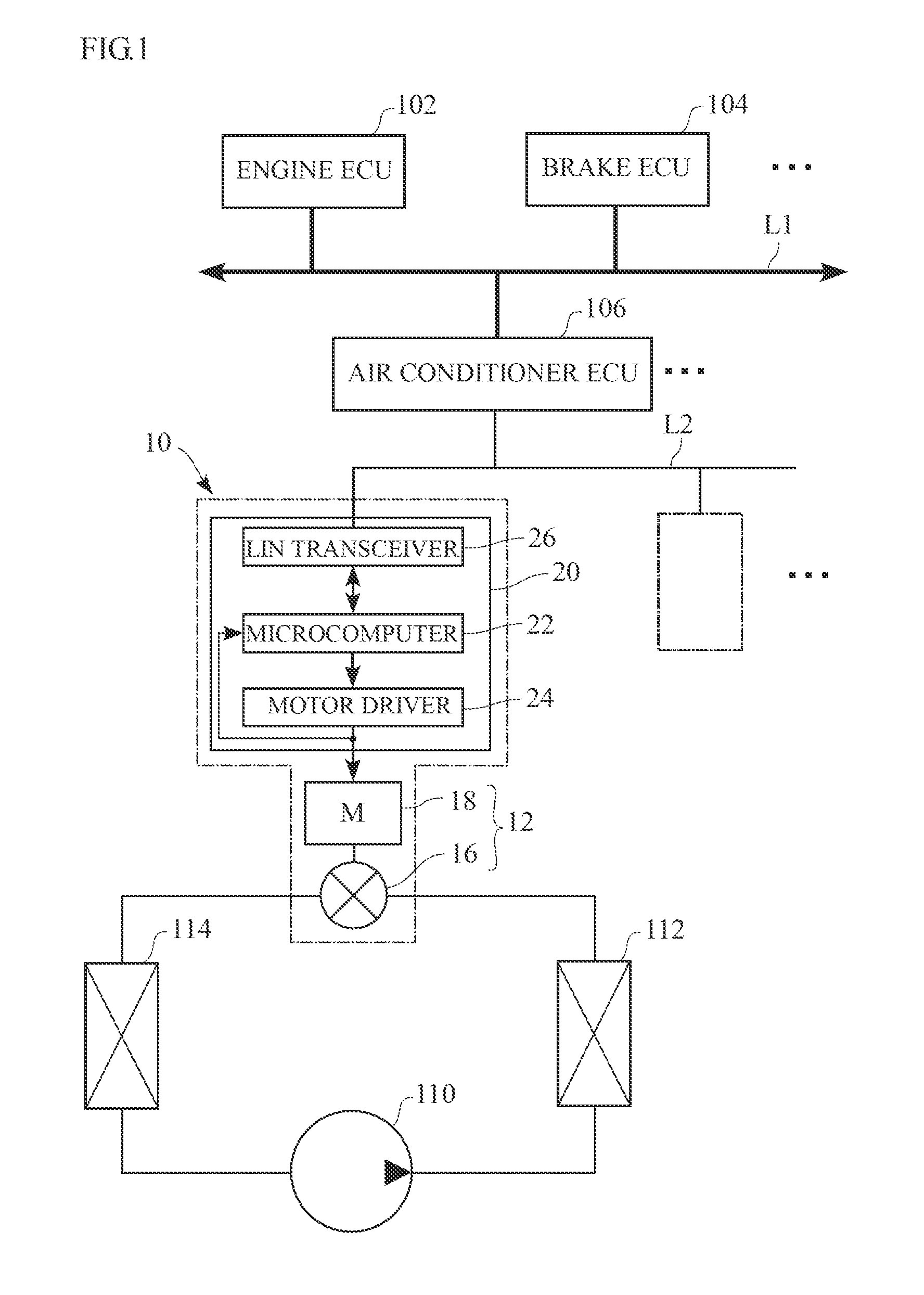
[0023]FIG. 1 is a diagram illustrating a system to which a motor operated valve apparatus according to an embodiment is applicable.

[0024]A motor operated valve apparatus 10 is applicable to an air conditioning system, which is part of a vehicle control system. The motor operated valve apparatus 10 is formed by an integral assembly of a motor operated valve 12, which functions as an expansion valve in a refrigeration cycle, and a motor operated valve controller 20 for controlling the motor operated ...


PUM


Abstract

A motor operated valve apparatus includes: a motor driven valve; a drive unit configured to drive the motor; a control unit configured to control the drive unit; and a communication unit configured to communicate with an external controller. The control unit starts control of the motor operated valve according to a command from the external controller; drives the motor in a valve closing direction at start of the control, detects a load on the motor based on a drive pulse output by the drive unit for driving the motor, and sets a driven state when the detected load reaches a predetermined reference value to be a valve switching point of a valve section; and drives the motor relative to the valve switching point of the valve section to perform control so that an opening degree of the valve section becomes a value corresponding to a control command value.

Description

CLAIM OF PRIORITY[0001]This application claims priority to Japanese Patent Application No. JP2015-090899, filed on Apr. 27, 2015, of which is incorporated herein by reference.BACKGROUND OF THE INVENTION[0002]1. Field of the Invention[0003]The present invention relates to a motor driven valve and a controller therefor.[0004]2. Description of the Related Art[0005]A refrigeration cycle in an automotive air conditioner generally includes a compressor for compressing circulating refrigerant, a condenser for condensing the compressed refrigerant, an expansion valve for throttling and expanding the condensed liquid refrigerant and delivering the resulting spray of gas-liquid mixture refrigerant, and an evaporator for evaporating the misty refrigerant and cooling the air in a vehicle interior by evaporative latent heat. For the expansion valves, mechanical expansion valves have been widely used. Such a mechanical expansion valve senses the temperature and the pressure of refrigerant at an o...

Claims


Application Information

Patent Timeline
IPC IPC(8): F25B41/06F16K31/04H02P8/04H02P8/26H02P8/30
CPCF25B41/062H02P8/26F16K31/046H02P8/04H02P8/30F16K1/32F16K1/36F16K31/04F16K37/0041F25B41/35F16K31/50F25B49/02F25B2600/2513F25B2700/197F25B2700/21175Y02B30/70
Inventor TAKAHASHI, KAZUSHI
Owner TGK
Why Eureka
Try Eureka