Automatic driving vehicle system

a technology of automatic driving and vehicle system, applied in the direction of instruments, scene recognition, navigation instruments, etc., can solve the problem that the ride quality of the vehicle sometimes becomes wors

Active Publication Date: 2016-10-27
TOYOTA JIDOSHA KK
View PDF3 Cites 26 Cited by
  • Summary
  • Abstract
  • Description
  • Claims
  • Application Information

AI Technical Summary

Problems solved by technology

Therefore, in the related automatic driving vehicle system, the ride quality of the vehicle sometimes becomes worse, in the case where the vehicle slightly departs from the track on which the vehicle runs.

Method used


Image

  • Automatic driving vehicle system
  • Automatic driving vehicle system
  • Automatic driving vehicle system

Examples


first embodiment

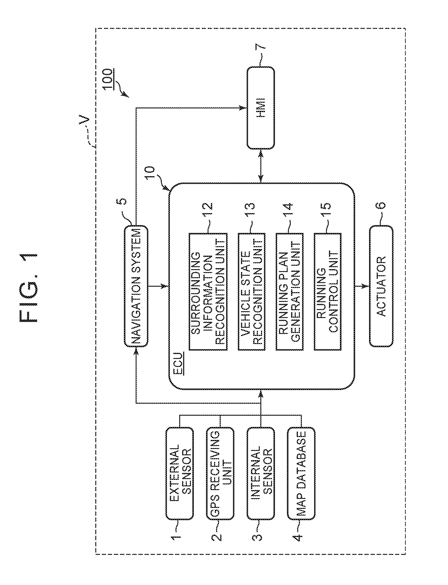
[0028]FIG. 1 is a block diagram showing a configuration of an automatic driving vehicle system 100 according to a first embodiment. As shown in FIG. 1, the automatic driving vehicle system 100 is mounted in a vehicle V such as an automobile. The automatic driving vehicle system 100 includes an external sensor 1, a GPS [Global Positioning System] receiving unit 2, an internal sensor 3, a map database 4, a navigation system 5, an actuator 6, an ECU [Electronic Control Unit]10, and an HMI [Human Machine Interface]7.

[0029]The external sensor 1 is detection equipment to detect the surrounding information of the vehicle V. The external sensor 1 includes at least one of a camera, a radar and a LIDAR [Laser Imaging Detection and Ranging].

[0030]The camera is an imaging device to image the surround of the vehicle V. The camera, for example, is provided on the vehicle interior side of the vehicle V relative to a windshield. Alternatively, the camera may be provided on the exterior of the vehic...

second embodiment

[0096]Next, a second embodiment will be described. In the description of the embodiment, differences from the first embodiment are described in detail. For elements identical or corresponding to those in the first embodiment, identical reference characters are used, and repetitive descriptions are omitted. FIG. 8 is a block diagram showing a configuration of an automatic driving vehicle system 100A according to the second embodiment. The automatic driving vehicle system 100A includes the external sensor 1, the GPS receiving unit 2, the internal sensor 3, the map database 4, the navigation system 5, the actuator 6, a first ECU 10A, a second ECU 10B, and the HMI 7. Here, the embodiment is different from the first embodiment in that the running plan generation unit 14 and the running control unit 15 are included in different ECUs. Specifically, the running control unit 15 may be included in a second ECU.

[0097]The first ECU 10A and the second ECU 10B control the automatic running of the...

third embodiment

[0104]Next, a third embodiment will be described. In the description of the embodiment, differences from the first embodiment are described in detail. For elements identical or corresponding to those in the first embodiment, identical reference characters are used, and repetitive descriptions are omitted. FIG. 9 is a block diagram showing a configuration of an automatic driving vehicle system 100B according to the third embodiment. The automatic driving vehicle system 100B includes the external sensor 1, the GPS receiving unit 2, the internal sensor 3, the map database 4, the navigation system 5, an actuator unit 60, an ECU 20, and the HMI 7. Here, the embodiment is different from the first embodiment mainly in that an actuator control unit (actuator controller) 62 of the actuator unit 60 controls an actuator 61 based on the control band.

[0105]The ECU 20 controls the automatic running of the vehicle V. The ECU 20 is an electronic control unit including a CPU, a ROM, a RAM and the li...


PUM


Abstract

An automatic driving vehicle system includes: a surrounding information recognition unit that recognizes surrounding information of a vehicle; a vehicle state recognition unit that recognizes a vehicle state of the vehicle; a running plan generation unit that generates a running plan based on the surrounding information of the vehicle and that generates a control band of a target control value for the vehicle in the running plan, based on at least one of the vehicle state and the surrounding information; a first computation unit that computes a command control value such that the vehicle state becomes a target vehicle state corresponding to the target control value, based on the running plan, the vehicle state and the control band; and an actuator that controls the running of the vehicle based on the command control value. The system may also include an actuator control unit.

Description

CROSS-REFERENCE TO RELATED APPLICATIONS[0001]The disclosure of Japanese Patent Application No. 2015-090260 filed on Apr. 27, 2015 including the specification, drawings and abstract is incorporated herein by reference in its entirety.BACKGROUND[0002]1. Technical Field[0003]This disclosure relates to an automatic driving vehicle system.[0004]2. Description of Related Art[0005]As described in US 2010 / 0228420 A, for example, there is an automatic driving vehicle system that controls the running of a vehicle. Such an automatic driving vehicle system, for example, calculates a track on which the vehicle should run, and controls the steering such that the vehicle runs on the calculated track.[0006]The situation of the vehicle differs between a case where the vehicle slightly departs from the track on which the vehicle should run, and a case where the vehicle greatly departs from the track on which the vehicle should run. However, the related automatic driving vehicle system controls the ru...

Claims


Application Information

Patent Timeline
Patent Type & Authority Applications(United States)
IPC IPC(8): G05D1/02
CPCG05D1/0212G05D1/0251G05D2201/02G05D1/0274G05D1/0257B62D1/28B62D15/0255G01C21/3415G05D1/021G05D1/0214B62D15/025B60W30/10B60W40/02G06V20/58G06V10/10B60W60/001B60W2050/0002G08G1/16
Inventor KINDO, TOSHIKIWATANABE, YOSHINORI
Owner TOYOTA JIDOSHA KK
Why Eureka
Try Eureka