Sole Structure for a Sport Shoe

a technology for sports shoes and soles, applied in the direction of uppers, bootlegs, stiffners, etc., can solve the problems of insufficient, further increase of accelerating force, and inadequate conformity of prior-art structures, so as to achieve greater resiliency, increase accelerating force, and increase hardness

Active Publication Date: 2016-11-03
MIZUNO CORPORATION
View PDF27 Cites 16 Cited by
  • Summary
  • Abstract
  • Description
  • Claims
  • Application Information

AI Technical Summary

Benefits of technology

[0006]According to the present invention, since the plate-like member of a higher hardness than that of the sole body is provided at the position corresponding to the toes of the foot on the foot sole contact surface side of the sole body, when a load is applied to the sole body from the toes during activities, the load acts on the soft sole body through the hard plate-like member. At this moment, compared to the case in which the load from the toes is imparted directly to the sole body and the soft sole body is thus locally deformed such that the load is absorbed by the sole body, the load from the toes is imparted to the sole body through the hard plate-like member thus restraining a local deformation of the sole body to prevent the load from the toes from being absorbed by the sole body. Since a greater resiliency can thus be achieved accelerating force can be increased during activities. As a result, quick movements can be achieved. For example, one can quickly move onto a dash, sidestep and jumping that require a push-off motion of the toes.
[0007]The plate-like member may be located at a position directly under a first distal phalanx to a fourth distal phalanx of the foot. In this case, the load at the time of the push-off motion can be effectively transmitted to the plate-like member.
[0008]The plate-like member may extend substantially in a foot width direction along the toes and have a short length in a foot length direction at a region between a first toe and a second toe. In this case, on opposite sides of a region between the first toe and the second toe, a region on the first toe side and a region on the second toe side are easy to bend respectively in the foot width direction, thereby smoothly transferring the load (strictly speaking, the center of foot pressure) in either case in which the foot pushes off on the first toe or on the fourth toe. As a result, quick movements due to an increase of accelerating force during activities can be achieved and at the same time transfer of the cen

Problems solved by technology

In the structure described in the above publication, the wavy corrugated sheet, which is disposed at the region extending from the midfoot part of the midsole to the position near the thenar eminence of the forefoot part, enabled an increase of resiliency to some degree when impacting the ground o

Method used


Image

  • Sole Structure for a Sport Shoe
  • Sole Structure for a Sport Shoe
  • Sole Structure for a Sport Shoe

Examples


first embodiment

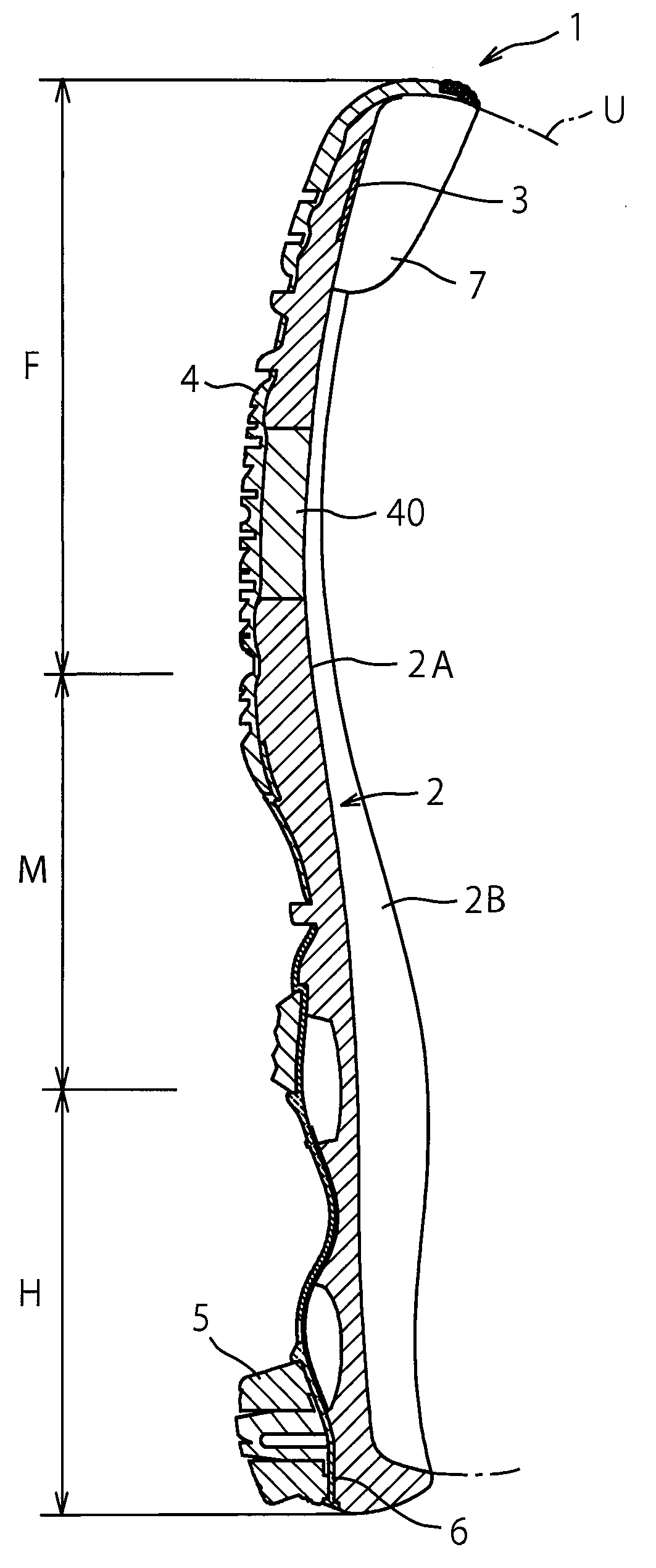
[0027]FIGS. 1 to 6 show a sole structure for a sport shoe according to a first embodiment of the present invention. Here, an indoor shoe used in indoor sports such as volleyball, handball or the like is taken as an example of the sport shoe.

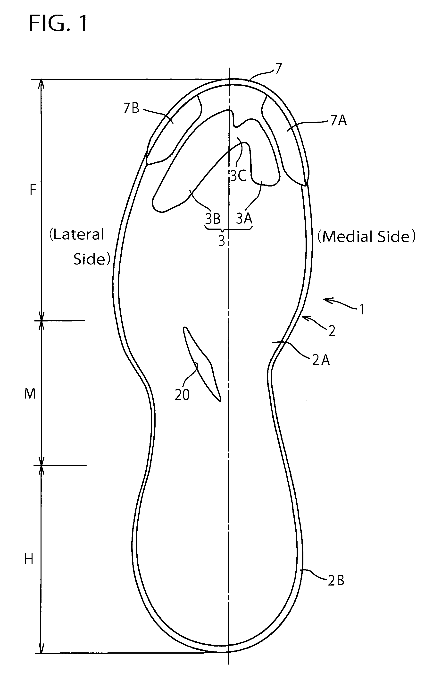
[0028]As shown in FIGS. 1 to 3, Sole structure 1 according to the present embodiment includes a sole body 2. The sole body 2 has a heel region H, a midfoot region M, and a forefoot region F that respectively correspond to a heel part, a midfoot part, and a forefoot part of a foot of a shoe wearer. The sole body 2 extends longitudinally from the heel region H through the midfoot region M to the forefoot region F. The sole body 2 has a foot sole contact surface 2A that is disposed on a foot sole contact side of the wearer.

[0029]On the foot sole contact surface 2A of the sole body 2, there is formed an upraised portion 2B that rises upwardly (i.e. out of the pages of FIGS. 1 and 2, to the right side of FIG. 3) along an approximately entire outer cir...

second embodiment

[0053]FIGS. 12 and 13 show a sole structure for a sport shoe according to a second embodiment of the present invention. In these drawings, the same reference numbers as those of the first embodiment indicate identical or similar elements.

[0054]The second embodiment differs from the above-mentioned first embodiment in that respective protruding portions 7A′, 7B′ of the toe guard 7 protrude further inwardly than the respective protruding portions 7A, 7B of the toe guard 7 in the first embodiment and the plate-like member 3 in the first embodiment is not provided. In this case, the protruding portion 7A′ corresponds to the first plate-like portion 3A in the first embodiment and the protruding portion 7B′ corresponds to the second plate-like portion 3B in the first embodiment. Also, in this case, a member corresponding to the narrow part 3C in the first embodiment is not provided and there is formed a gap between the protruding portions 7A′ and 7B′.

[0055]In other words, in this second e...

first alternative embodiment

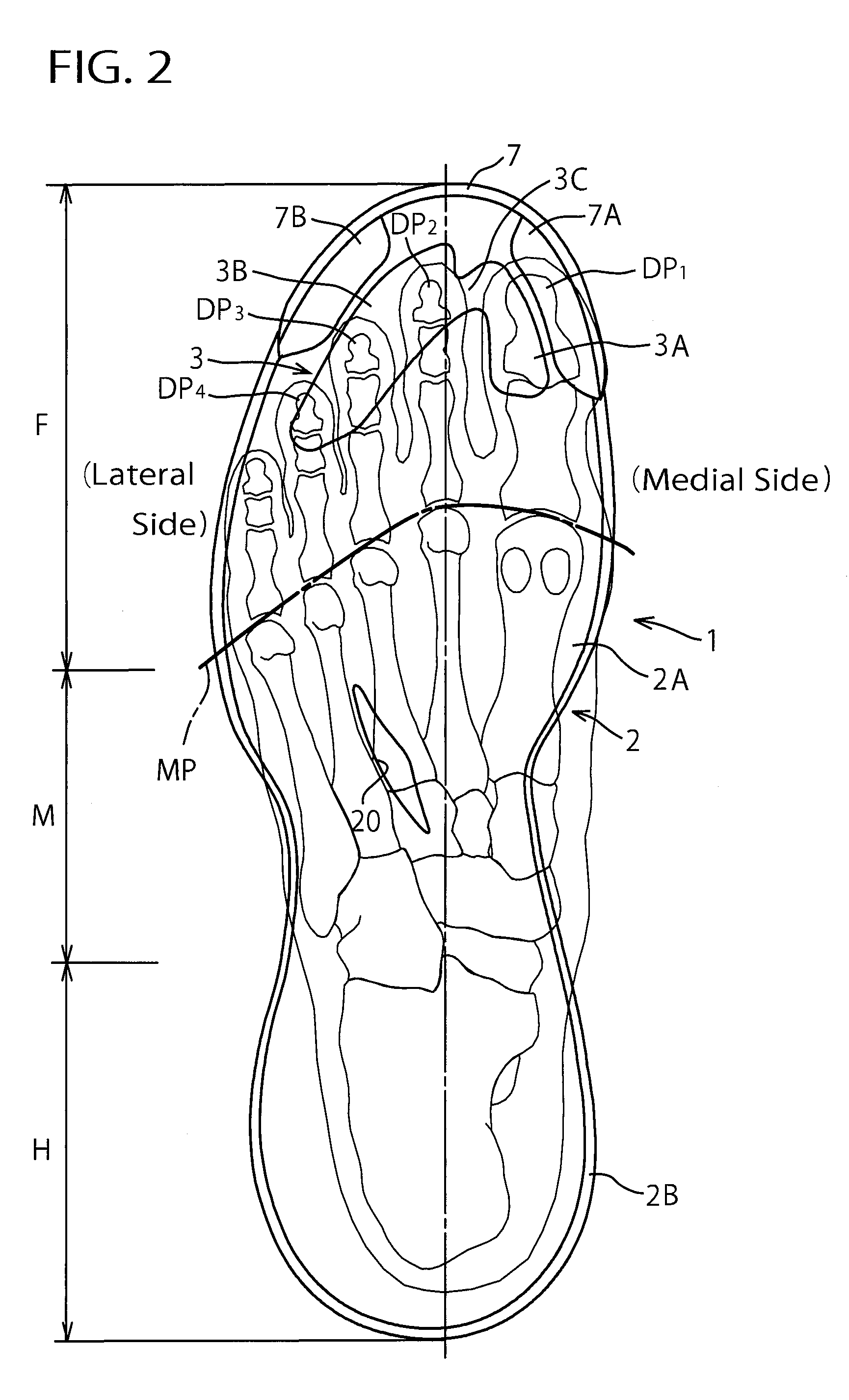
[0061]In the first embodiment, as the plate-like member 3, a deformed M-shaped member in a planar shape was taken for an example (see FIG. 1), but the planar shape of the plate-like member 3 is not limited to such a shape. The plate-like member 3 may include the first plate-like portion 3A that overlaps at least partially with the first toe (preferably, the first distal phalanx), the second plate-like portion 3B that overlaps at least partially with the second to fourth toes (preferably, the second to fourth distal phalanges), and the narrow part 3C disposed therebetween. Other any shapes can be adopted.


PUM

PropertyMeasurementUnit
Electric chargeaaaaaaaaaa
Lengthaaaaaaaaaa
Forceaaaaaaaaaa

Abstract

A sole structure for a sport shoe is proposed that can increase accelerating force during activities and achieve quick movements. A sole assembly 1 for an indoor shoe includes a sole body 2 formed of a soft elastic member and a plate-like member 3 that is disposed at a position right under the first to fourth distal phalanx DP1-DP4 of the foot on a foot sole contact surface 2A of the sole body 2 and that has a higher hardness than that of the sole body 2. The plate-like member 3 extends arcuately substantially in the foot width direction along the toes and has a narrow part 3C of a short length in the foot length direction at a region between the first toe and the second toe.

Description

TECHNICAL FIELD[0001]The present invention relates generally to a sole structure for a sport shoe, and more particularly, to an improved sole structure that can increase accelerating force during activities and enables quick movements.BACKGROUND ART[0002]The applicant of the present invention proposed a sole structure for a sport shoe such as shown in Japanese Patent No. 3215664. In the sole structure shown in the patent publication, the wavy corrugated sheet is interposed inside the midsole of a soft elastic member and it extends from the heel part of the midsole through the midfoot part to the position near the thenar eminence of the forefoot part. Thereby, a lateral swing can be prevented at the region from the heel part to the midfoot part of the midsole after impacting the ground, thus securing stability during running (see para. [0091] and FIGS. 5-7).[0003]In the structure described in the above publication, the wavy corrugated sheet, which is disposed at the region extending ...

Claims


Application Information

Patent Timeline
IPC IPC(8): A43B13/18A43B13/04A43B7/14A43B7/08A43B23/08A43B5/00A43B13/12
CPCA43B13/186A43B5/00A43B13/04A43B7/145A43B13/188A43B7/087A43B23/087A43B13/12
Inventor IUCHI, KAZUNORIKURAYAMA, KEIJIKURODA, KIYOTAKA
Owner MIZUNO CORPORATION
Why Eureka
Try Eureka