
Methods, systems, and devices for optimal positioning of sensors

a sensor and optimal positioning technology, applied in the field of electronic systems, can solve the problems of misapplied sensor, sensor positioning is not accurate for patients, sensor spacing is significantly different from what was intended for the sensor, etc., to achieve the effect of improving the feedback regarding sensor positioning

Active Publication Date: 2016-11-03
LIFESCAN IP HLDG LLC
View PDF2 Cites 17 Cited by
  • Summary
  • Abstract
  • Description
  • Claims
  • Application Information

AI Technical Summary

Benefits of technology

The present invention provides various embodiments that can improve the feedback regarding sensor positioning. These embodiments can help users and home-care providers position sensors accurately and detect conditions that may interfere with sensor readings.

Problems solved by technology

Given this specificity, it can be difficult for caregivers to apply sensors correctly.
However, in such a circumstance, not only are the placement of the sensor and measurement method different from what was intended, but the spacing between the emitters and detector is also significantly different from what was intended for the sensor.
Thus, the misapplied sensor will not give accurate readings for the patient.
Other misapplications of a sensor include placement on a site which, although positionally correct, is not suitable for optimal measurements.
This situation may exist, for example, when the physical characteristics of the site are unsatisfactory to yield reliable measurements, e,g., due to sweat, hair, or position of subcutaneous fat.
For example, although an oximeter calibrated for the pointer finger may be intended for use with either finger, differences between the patient's two pointer fingers may only permit the oximeter to be effectively used with one of those fingers.
Moreover, the user or health care provider may unwittingly or carelessly position a physiologic sensor in whole or in part over an article of clothing.

Method used


Image

  • Methods, systems, and devices for optimal positioning of sensors
  • Methods, systems, and devices for optimal positioning of sensors
  • Methods, systems, and devices for optimal positioning of sensors

Examples


Embodiment Construction

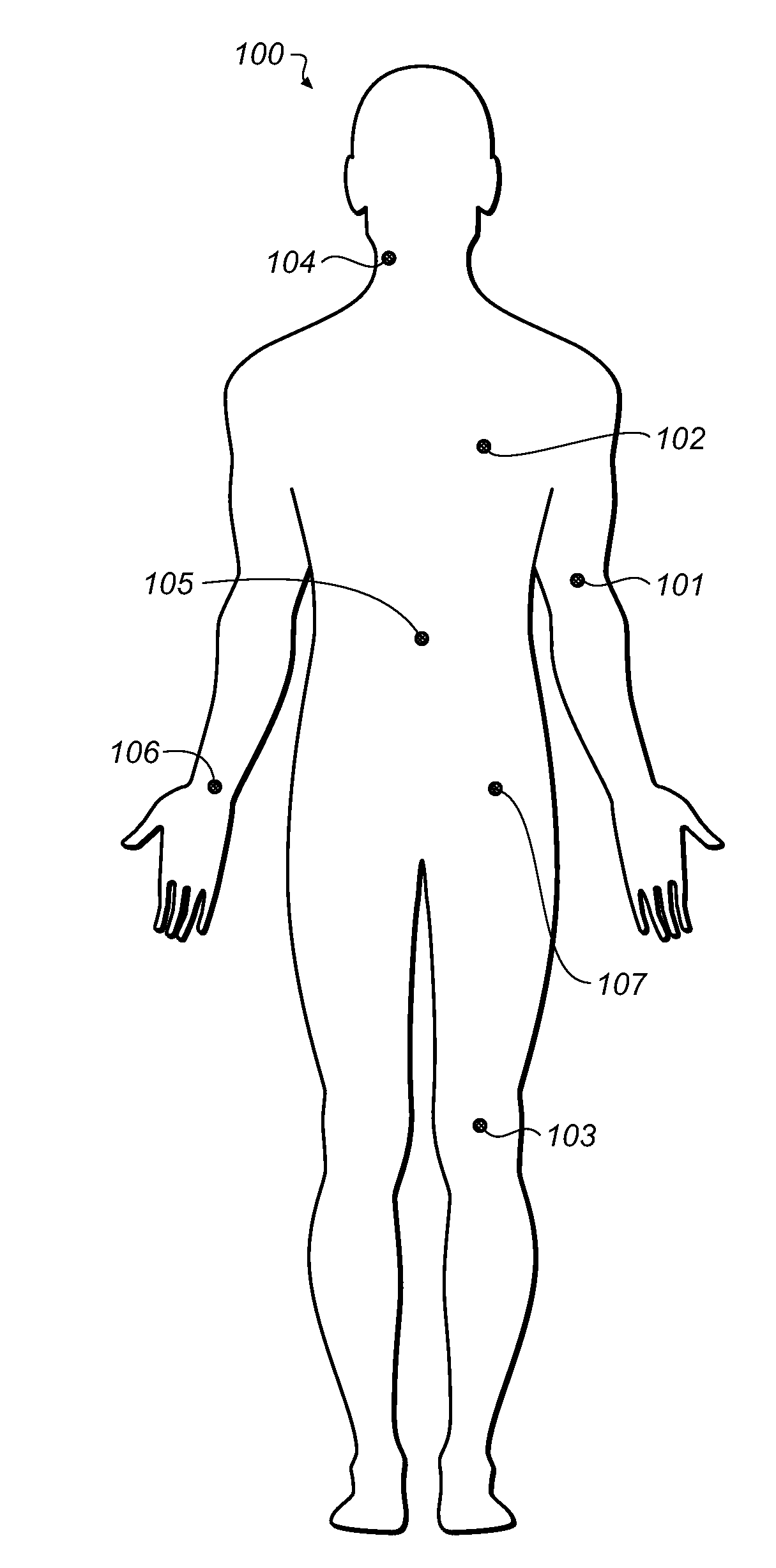
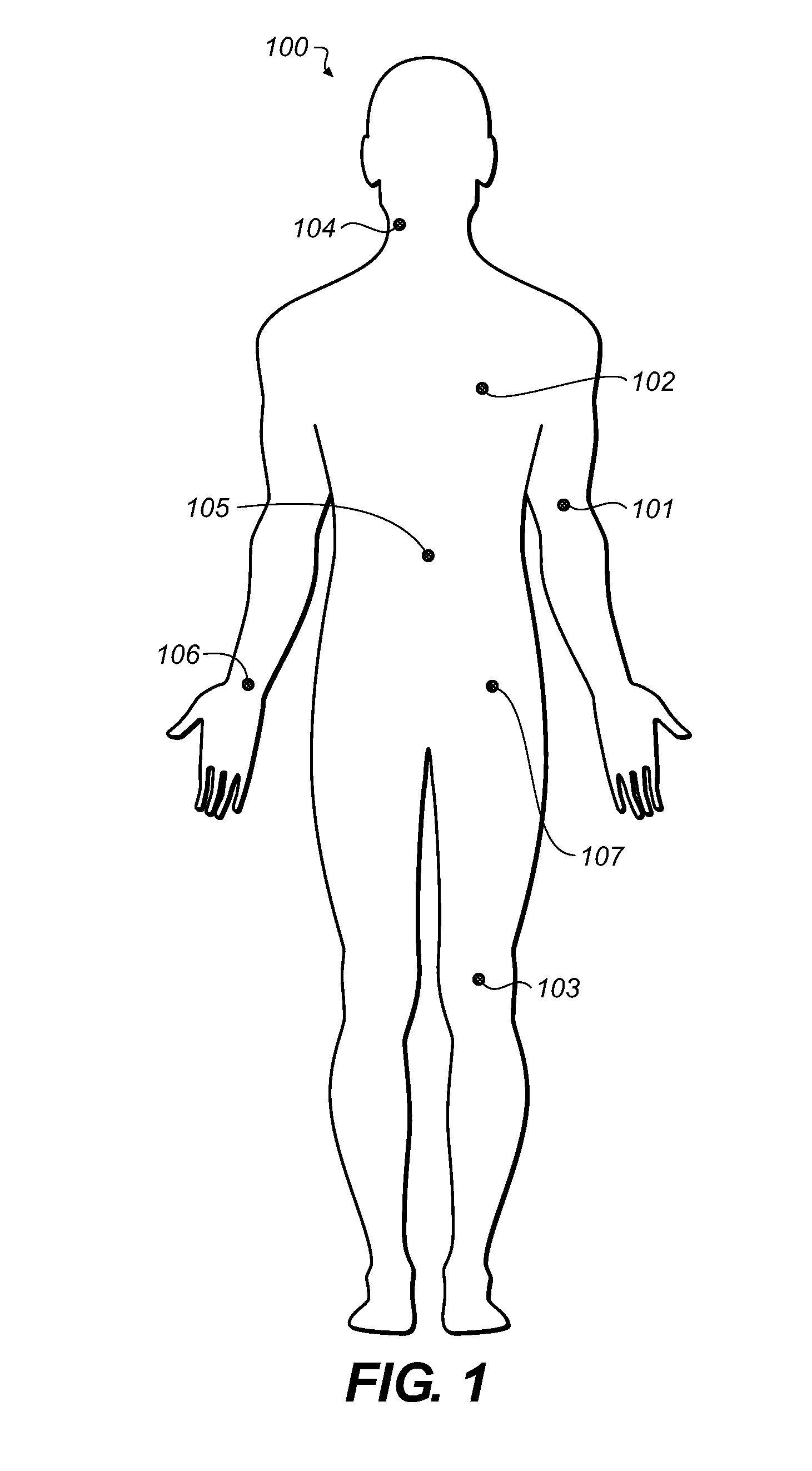
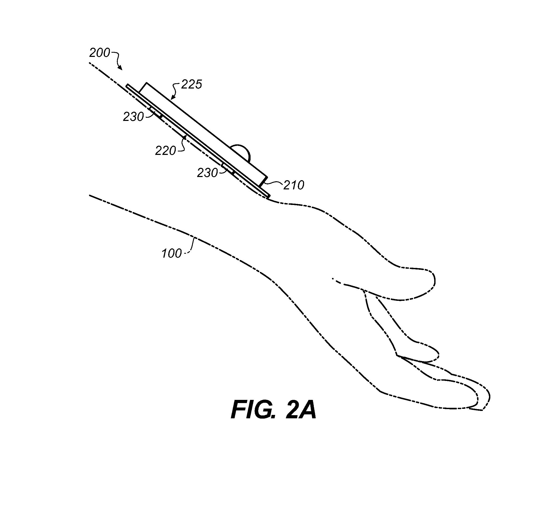
[0037]The following detailed description should be read with reference to the drawings, in which like elements in different drawings are identically numbered. The drawings, which are not necessarily to scale, depict selected embodiments and are not intended to limit the scope of the invention or the attached claims.

[0038]As used herein, the terms “about” or “approximately” for any numerical values or ranges indicate a suitable dimensional tolerance that allows the part or collection of components to function for its intended purpose as described herein. More specifically, “about” or “approximately” may refer to the range of values not at least ±10% of the recited value, e.g. “about 90%” may refer to the range of values from 81% to 99%. As used herein, the phrase “electrical signal” or “signal” is intended to include direct current signals, alternating signals, or any signal within the electromagnetic spectrum. The terms “processor,”“microprocessor,” and “microcontroller” are intende...


PUM


Abstract

A biomedical sensor has conducting elements disposed at least partly over a skin-facing surface. A sensing element detects a signal representative of a physiological parameter of a body using the conducting elements. A storage device stores a physiological model. A processor determines sensor placement quality by comparing the signal to the model and operates an indicator to indicate the determined quality. A method of measuring using the sensor includes computing a measurement acceptance criterion using numerous measurements, determining whether a subsequent test measurement corresponds to the measurement acceptance criterion obtained from the computing step, and indicating the results via the indicator. A system for measuring a physiological property of the body includes the sensor, a user interface device to receive measurements from the sensor, and a processor associated with the user interface device and configured to provide feedback if the measurement does not meet a selected acceptance criterion.

Description

PRIORITY[0001]This international Patent Application claims the benefits of priority under the Paris Convention and 35 USC §119 to prior filed U.S. Provisional Patent Application Ser. No. 61 / 922,097 filed on Dec. 31, 2013, which prior application is hereby incorporated by reference.TECHNICAL FIELD[0002]This application relates generally to the field of electronic systems for monitoring biological properties of a user's body, and more specifically to medical monitoring systems.BACKGROUND[0003]The use of various types of sensors to evaluate one or more physiological characteristics or parameters of a patient is well known. For example, optical pulse oximetry sensors measure the level of oxygen saturation (SpO2) in a patient's blood. Typically, a light emitting diode (LED) transmits optical radiation of several different wavelengths, e.g., visible and infrared, through blood and tissue of a predetermined portion of a patient's body, such as the wrist or finger. A photodetector detects t...

Claims


Application Information

Patent Timeline
IPC IPC(8): A61B5/00A61B5/0205A61B5/0488A61B5/0478A61B5/024A61B5/053A61B5/145A61B5/296A61B5/332
CPCA61B5/684A61B5/02405A61B5/053A61B5/0008A61B5/0006A61B5/02055A61B5/14532A61B5/0478A61B5/0531A61B5/0533A61B5/742A61B5/6844A61B5/024A61B5/0488A61B2560/0223A61B5/021A61B5/0002A61B5/065A61B5/291A61B5/389
Inventor FOUGERE, RICHARDLEE, CURTISWALSH, RYAN
Owner LIFESCAN IP HLDG LLC
Learn More