
Rear view camera system for a motor vehicle

a camera system and rear view technology, applied in vehicle components, instruments, computing, etc., can solve the problems of increasing the variability of recording the surrounding area, and the danger of damage to the camera optical system

Inactive Publication Date: 2016-11-03
HUF HULSBECK & FURST GMBH & CO KG
View PDF19 Cites 9 Cited by
  • Summary
  • Abstract
  • Description
  • Claims
  • Application Information

AI Technical Summary

Benefits of technology

The invention is a rear view camera system for vehicles that allows the camera optical system to be moved from rest position to recording position by rotating around an adjustable axis. The system has a compact structure and requires only a small mounting space. It also allows for different surrounding areas to be recorded by adjusting the rotation angle. The camera optical system can be quickly and easily rotated back to rest position for protection. The invention further provides an impact protection to prevent damage to the camera optical system when exposed to tough handling. The technical effects of the invention are a functional construction that is simple and cost-effective, as well as improved protection of the camera optical system.

Problems solved by technology

It results in the extension or exposure movement of the adjustable axis, thus moving the camera optical system out of the carrier assembly, which increases the variability of recording the surrounding area, as well as the recording range.
When during a recording position the camera optical system protrudes from the recess of the carrier assembly, there is the danger that the camera optical system is damaged, especially when the camera optical system is mounted on the tailboard of a pickup truck, which is exposed to tough and harsh handling.
As a result, the camera optical system can be retracted back into the recess of the carrier assembly when a correspondingly high force impacts the camera optical system from the outside, which would involve the danger of the camera optical system to be damaged.

Method used


Image

  • Rear view camera system for a motor vehicle
  • Rear view camera system for a motor vehicle
  • Rear view camera system for a motor vehicle

Examples


first embodiment

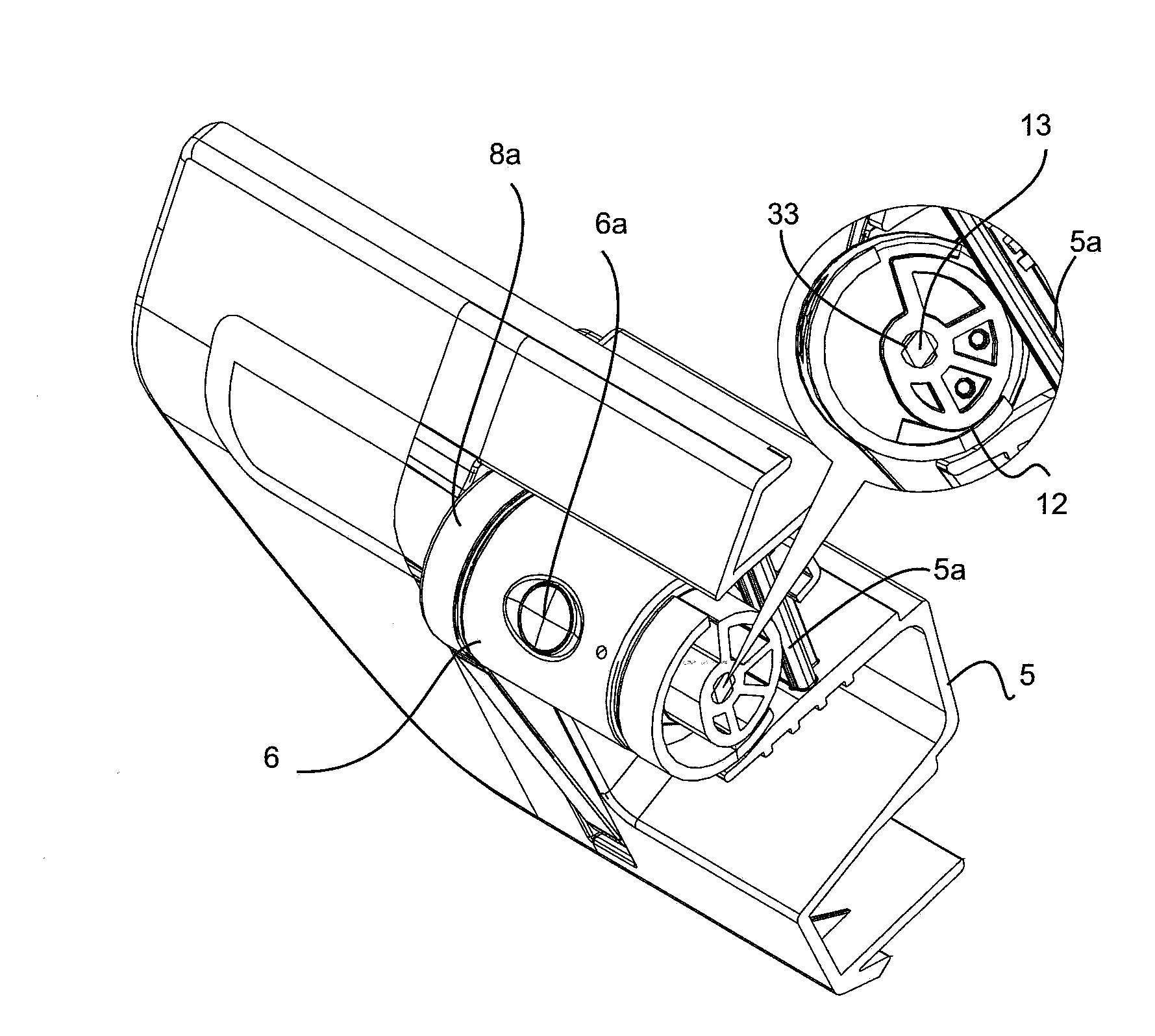
[0133]FIGS. 11 to 15 show an impact protection 70a, which is designed in the form of an elastic pressure spring. In this connection, the bar-like support element 50a is supported at the elastic pressure spring 51, wherein it also serves as an attachment for the eccentric component 12. Under compression of the elastic pressure spring 51, the bar or support element 50 can be shifted in relation to the carrier assembly 5 or into the recess 60. For this purpose, the support element 50a is incorporated in a guide 52 in which it is retained in movable fashion by means of a pressure spring 50a. The guide 52 of the support element 50a is shown in FIG. 12. When a force is exerted on the camera optical system 6 (or on the drive unit 7 of the camera optical system 6, which also protrudes from the carrier assembly), the camera optical system 6 can be pushed back into the carrier assembly 5 by power transmission of the eccentric component 12 against the compression force, i.e., the evasive force...

second embodiment

[0135]The first and second embodiment of the impact protection 70a, 70b, can be described in an abstract manner in such a way that the respective support element 50a, 50b is elastically coupled with the carrier assembly 5, so that the support element 50a, 50b can be moved and / or elastically deformed in relation to the carrier assembly 5 by overcoming the evasive force of the impact protection 70a, 70b.

[0136]FIGS. 19 to 21 show a third embodiment of the impact protection 70c. In contrast to the first and second embodiment, here the support element 5a is again designed in the form of a rigid bar, which is fixed at the carrier assembly 5. In the third embodiment, the eccentric component 12 represents the impact protection 70c. This impact protection 70c is characterized in that the eccentric component 12 has at least one outer peripheral region 12a that is designed in elastically deformable manner. The importance of this elastically deformable outer peripheral region 12a is subsequent...

third embodiment

[0137]FIGS. 22 to 24 show by means of a third embodiment a modification of the impact protection 70c. In this modification, the impact protection 70c has a two-part design and comprises a spring element 110 consisting of metal and a housing 200 of the camera optical system 6. At the same time, the spring element 110 is mounted at the housing 200 of the camera optical system 6 and forms the eccentric component 12, which is supported at the support element 5a when it is rotated about the adjustable axis 33. As a result, the camera optical system 6 assumes the position shown in FIG. 23, in which the camera optical system 6 protrudes from the recess 60 of the carrier assembly 5. The function of the impact protection shown 70c in FIGS. 22 to 24 corresponds to the operating modes of the embodiments shown in FIGS. 19 to 21, so that reference can be made to these embodiments. Even in the embodiment shown in FIG. 24, the spring element 110, which has an elastically deformable and semicircula...


PUM


Abstract

A rear view camera system for a motor vehicle includes a movable carrier assembly, a camera optical system, which is movable with the carrier assembly, and a drive unit coupled with the camera optical system. The camera optical system is pivoted in relation to the carrier assembly about an adjustable axis which is rotatably coupled with the drive unit and can be moved about the adjustable axis between a rest position and a recording position. These can be adjusted depending on the surrounding areas to be recorded. An eccentric component is coupled in movable fashion with the adjustable axis. A rotation of the eccentric component changes the distance between the adjustable axis and the support element so that the camera optical system can be moved to a recording position in which the camera optical system protrudes from the recess of the carrier assembly.

Description

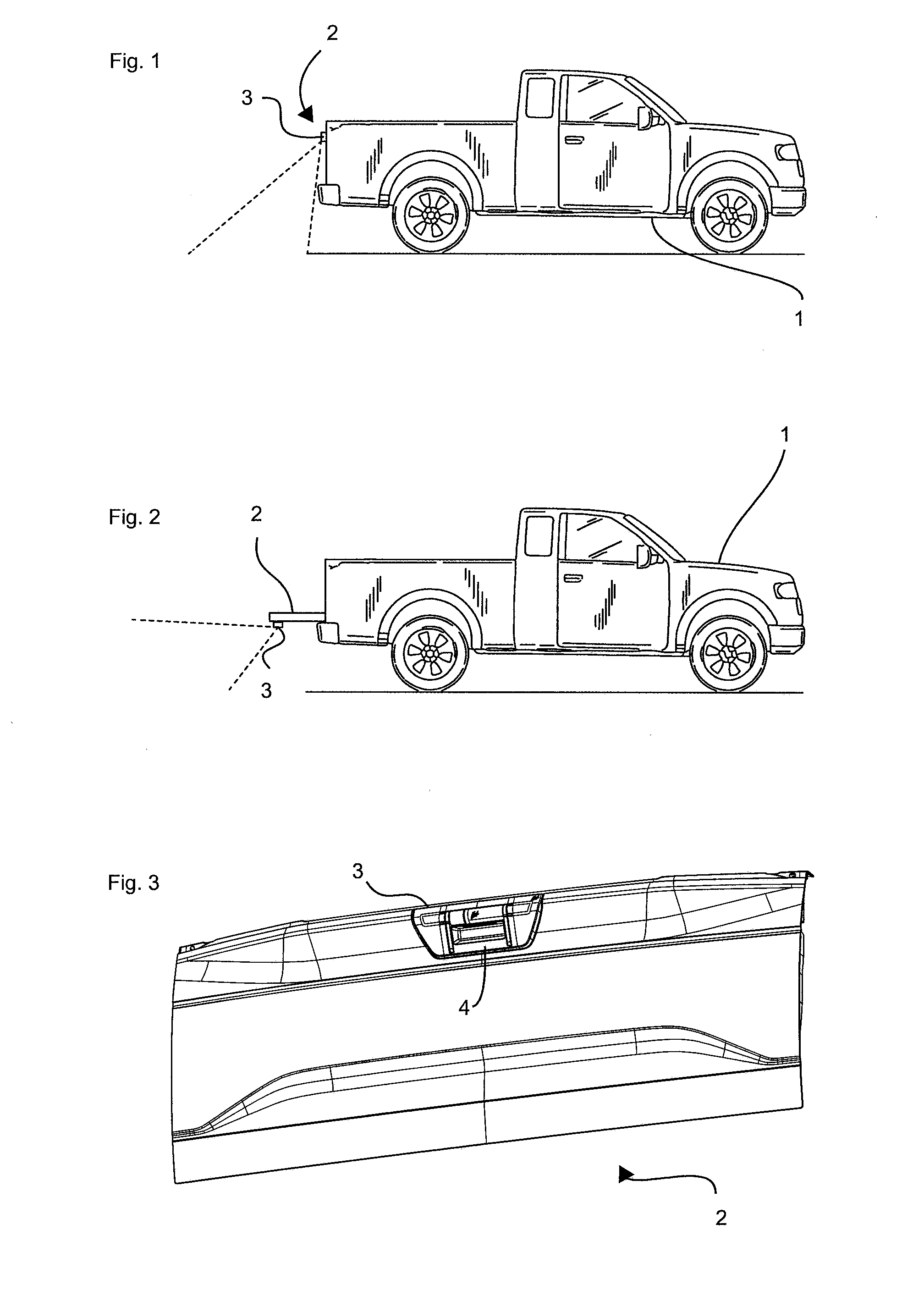
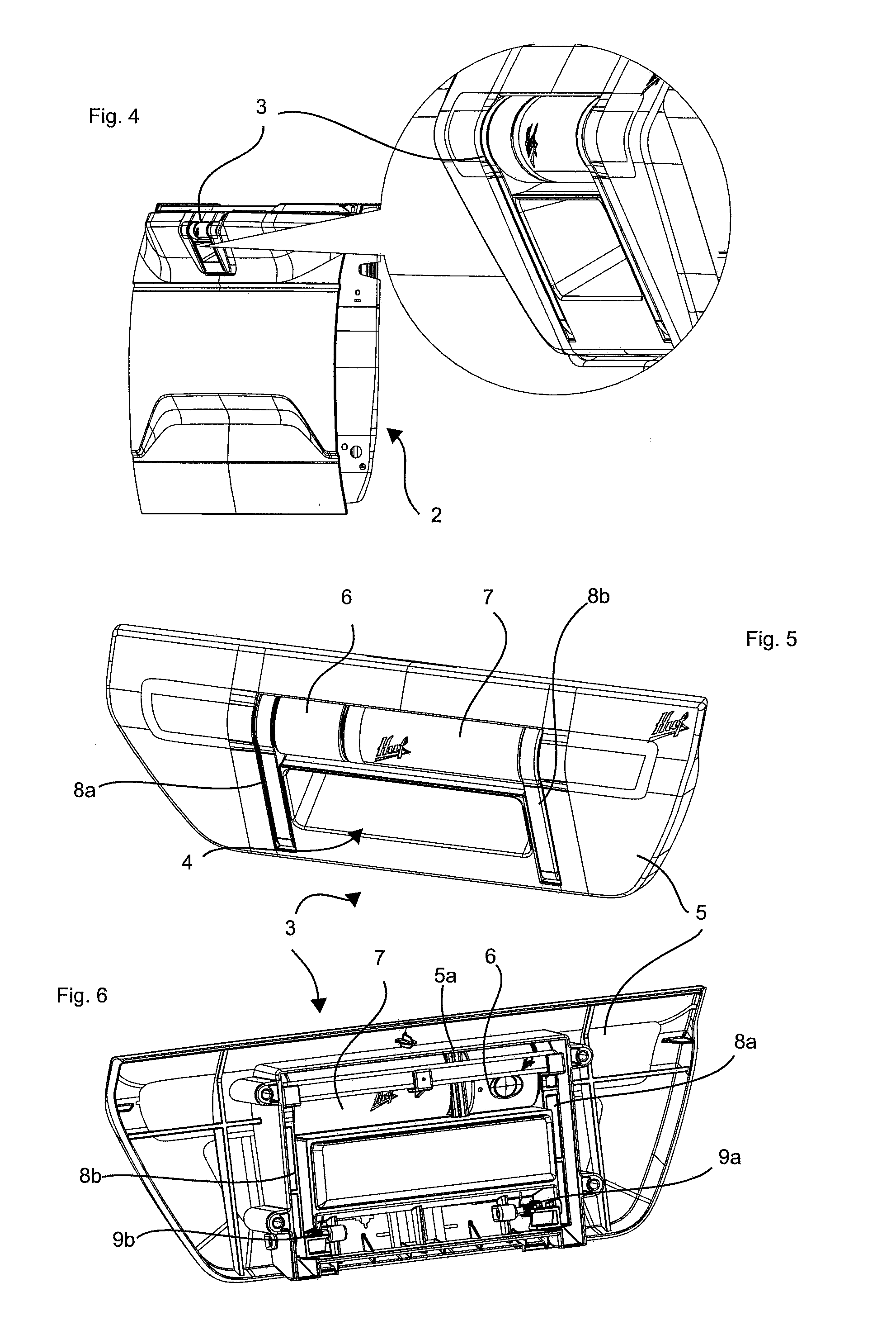
BACKGROUND[0001]The invention relates to a rear view camera system for a motor vehicle, comprising a carrier assembly which is arranged on a movable vehicle component of the motor vehicle, a camera optical system which is coupled in movable fashion with the carrier assembly and a drive unit which is coupled with the camera optical system, designed in such a way that the camera optical system can be moved to a rest position in which it is arranged in a recess of the carrier assembly, and to a recording position in which the camera optical system is able to record a surrounding area of the motor vehicle.[0002]Furthermore, the invention relates to a rear view camera system for motor vehicles. Rear view cameras are used in motor vehicles to provide the driver with an improved view of the area behind the rear end of the motor vehicle. For this purpose, a monitoring device is provided in the driver's cabin of the vehicle and a camera is fixed at the rear section of the vehicle or arranged...

Claims


Application Information

Patent Timeline
IPC IPC(8): B60R11/04G06K9/00G06V10/147
CPCB60R11/04B60R2011/0094B60R2011/004G06K9/00791B60R2011/0092G06V20/56G06V10/147
Inventor MOENIG, STEFANSCHEMBERG, LOTHARHILD, SVENGORENZWEIG, IGORBRESSER, CHRISTIAN
Owner HUF HULSBECK & FURST GMBH & CO KG
Learn More