
Phased array system for inspection of laser welds

a phased array system and laser weld technology, applied in the direction of measuring devices, instruments, analysing solids using sonic/ultrasonic/infrasonic waves, etc., can solve the problems of cracking, high heating and cooling rate, and small heat-affected zones as well

Active Publication Date: 2016-11-03
EDISON WELDING INSTITUTE INC
View PDF37 Cites 30 Cited by
  • Summary
  • Abstract
  • Description
  • Claims
  • Application Information

AI Technical Summary

Benefits of technology

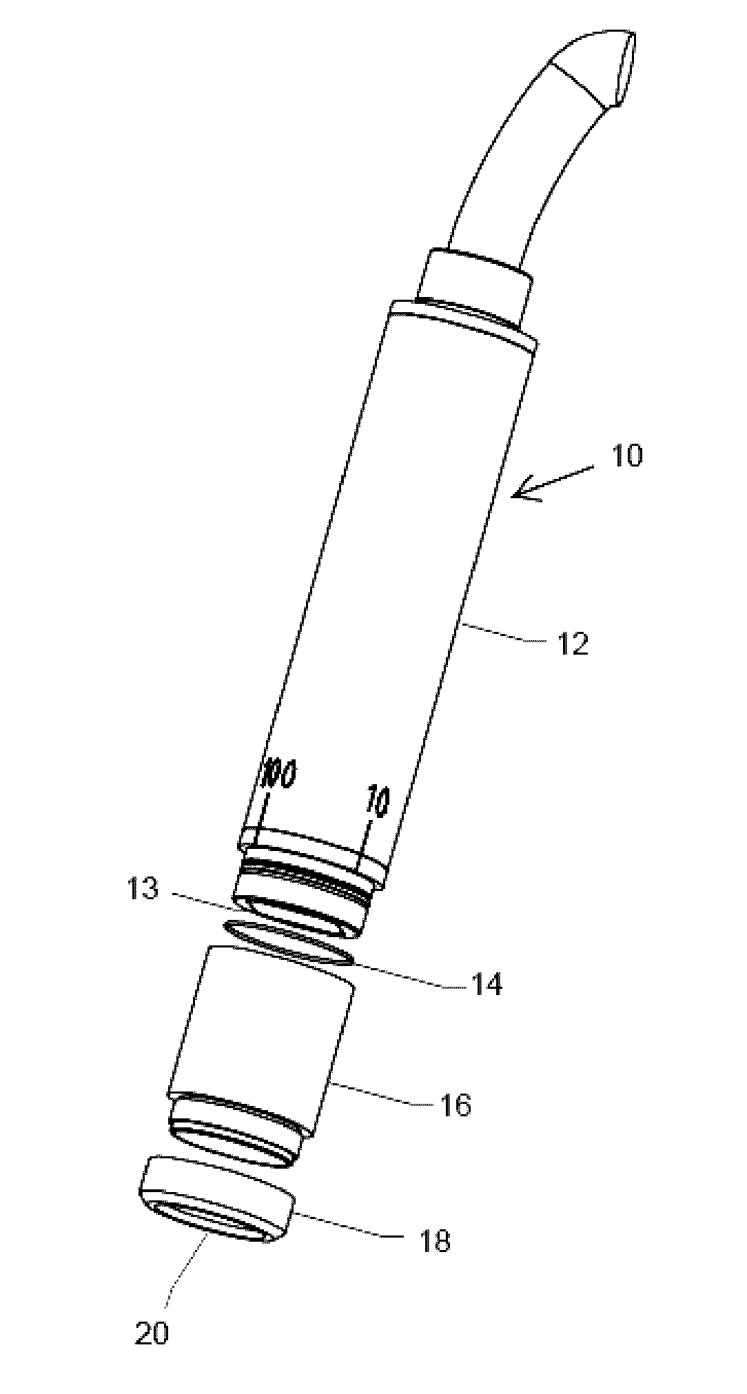
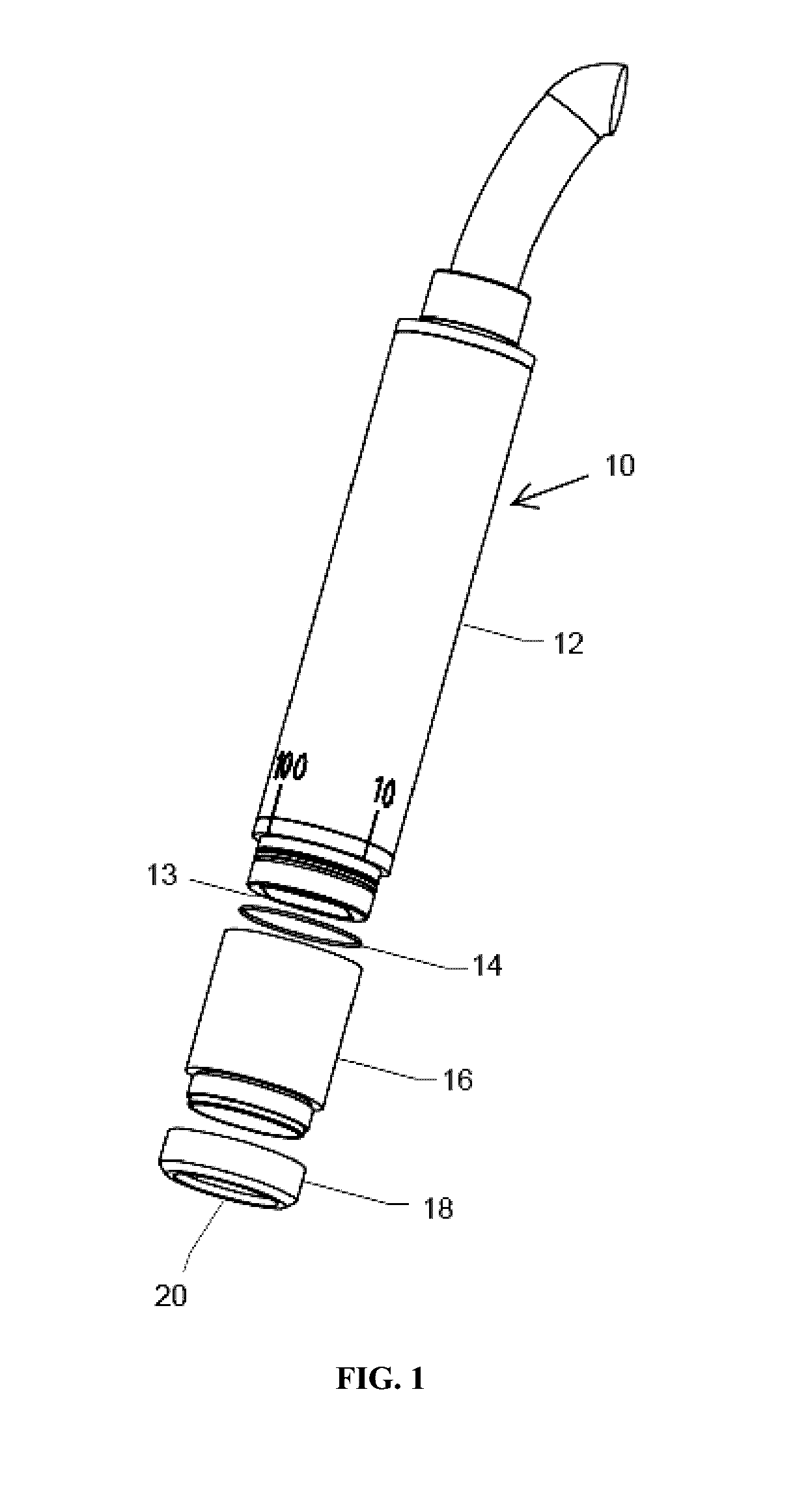
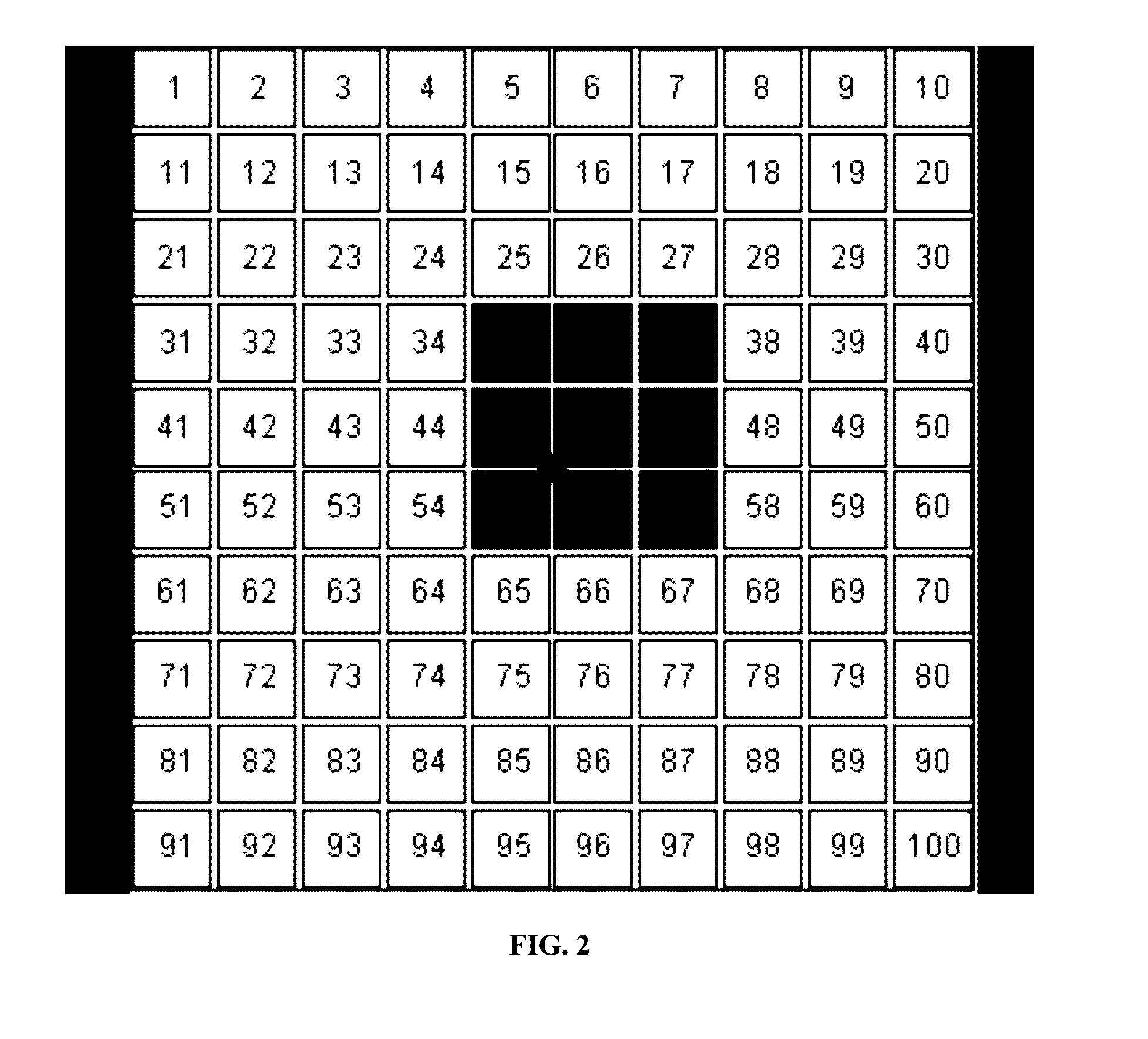
The present invention provides a system for non-destructively characterizing laser welds using a phased array probe with ultrasonic transducer elements arranged in an array. The probe is designed to conform to the contoured surface of a laser weld and transfer sound energy directly into it. A combination of materials including a flexible membrane and fluid filled chamber or solid sound delay material are used to improve the transfer of sound energy. The data processor includes software for processing the data received from the probe and generating color coded ultrasonic C-scan images of the characterized laser weld.

Problems solved by technology

Similar to electron beam welding, laser beam welding has a high power density (on the order of 1 MW / cm2) resulting in small heat-affected zones as well as high heating and cooling rates.
However, due to high cooling rates, cracking is a concern when welding high-carbon steels, and welds created by laser beam welding must often be evaluated for weld integrity.
Acoustic methods, however, do have certain limitations.
The most significant limitations include the requirement of a skillful operator for using the testing device and analyzing acoustic data, as well as the very subjective nature of identifying an inadequate bond or faulty weld joint.

Method used


Image

  • Phased array system for inspection of laser welds
  • Phased array system for inspection of laser welds
  • Phased array system for inspection of laser welds

Examples


Embodiment Construction

[0022]Exemplary embodiments of the present invention are now described with reference to the Figures. Although the following detailed description contains many specifics for purposes of illustration, a person of ordinary skill in the art will appreciate that many variations and alterations to the following details are within the scope of the invention. Accordingly, the following embodiments of the invention are set forth without any loss of generality to, and without imposing limitations upon, the claimed invention.

[0023]The present application incorporates by reference herein U.S. patent application Ser. No. 12 / 186,047 (U.S. Pat. No. 8,215,173); Ser. No. 13 / 468,502 (U.S. Pat. No. 9,063,059); and Ser. No. 14 / 183,643 (U.S. Pat. No. 9,037,419); in their entirety, for all purposes. With regard to the nomenclature used herein, the present invention is described as being useful for analyzing the integrity of laser welds between a first and second workpiece or upper and lower sheets of me...


PUM


Abstract

A system for non-destructively characterizing laser welds that includes at least one phased array probe that includes a plurality of ultrasonic transducer elements arranged in an array at one end of the probe, wherein the transducer elements are operative to both generate ultrasonic signals and to receive reflections thereof, wherein the transducer elements are further arranged into discrete subgroups, and wherein each subgroup may be activated independently of the other subgroups and at different time intervals; a combination of materials for allowing the probe to conform to a contoured surface of a laser weld while enabling sound energy to be transferred directly into a laser weld under test conditions, wherein the combination of materials further includes a flexible membrane mounted on the end of the probe and a fluid filled chamber material disposed between the membrane and the array of ultrasonic transducer elements; and a data processor in communication with the at least one phased array probe that includes software having at least one imaging algorithm for processing data received from the probe and generating color coded ultrasonic C-scan images of a characterized laser weld.

Description

CROSS-REFERENCE TO RELATED APPLICATIONS[0001]This patent application claims the benefit of U.S. Provisional Patent Application Ser. No. 62 / 144,118 filed on Apr. 7, 2015 and entitled “Matrix Phased Array System for Inspection of Laser Welds,” the disclosure of which is hereby incorporated by reference herein in its entirety and made part of the present U.S. utility patent application for all purposes.BACKGROUND OF THE INVENTION[0002]The present invention relates in general to inspection systems and devices for use in assessing the performance of industrial manufacturing processes, and more specifically to a nondestructive inspection or evaluation system for assessing the quality of welds created by laser beam welding.[0003]Laser beam welding is a welding technique for joining multiple pieces of metal through the use of one or more lasers. A laser beam provides a concentrated heat source that allows for the creation of narrow, deep welds at high welding rates. The laser welding proces...

Claims


Application Information

Patent Timeline
IPC IPC(8): G01N29/04
CPCG01N29/041G01N2291/106G01N2291/267G01N29/265G01N29/262G01N29/28G01N2291/044G01N2291/2638G01N29/0645G01N29/043
Inventor SPENCER, ROGERBOULWARE, PAUL C.NA, JEONG K.
Owner EDISON WELDING INSTITUTE INC
Learn More