
Device, Terminal, Method and Storage Medium for Improving Radio Frequency Link Receiving and Transmitting Performance

Inactive Publication Date: 2016-11-03
ZTE CORP
View PDF7 Cites 6 Cited by
  • Summary
  • Abstract
  • Description
  • Claims
  • Application Information

AI Technical Summary

Benefits of technology

The present invention provides a device, a mobile terminal, a method, and a storage medium for improving the receiving and transmitting performance of a radio frequency link. This is achieved by using a test device that connects to the radio frequency main switch and antennas in the transmitting and receiving links, and a computer program to execute the method. The invention reduces insertion losses, improves transmitting power, and enhances receiving sensitivity of the mobile terminal.

Problems solved by technology

Although this kind of power amplifiers has the features of small volume, light weight, high reliability, low cost and the like, and can exempt a user from designing an input / output matching network and a static working point and thus design time is saved, since an inductor L and a capacitor C in the matching network respectively consist of a gold wire and a gold foil, the tolerable power is comparatively small; and due to the small volume, the direct-current consumption power is comparatively large, the thermal resistance from the tube core to an element surface is large and consequently heat emission is comparatively serious.
As a result, the maximum output power of this kind of power amplifiers is about 28-30 dBm and it is difficult to reach higher output power; and in consideration of 1 dB compression point factor, the actually usable output power of this kind of power amplifier is only about 27-29 dBm.

Method used


Image

  • Device, Terminal, Method and Storage Medium for Improving Radio Frequency Link Receiving and Transmitting Performance
  • Device, Terminal, Method and Storage Medium for Improving Radio Frequency Link Receiving and Transmitting Performance
  • Device, Terminal, Method and Storage Medium for Improving Radio Frequency Link Receiving and Transmitting Performance

Examples


Embodiment Construction

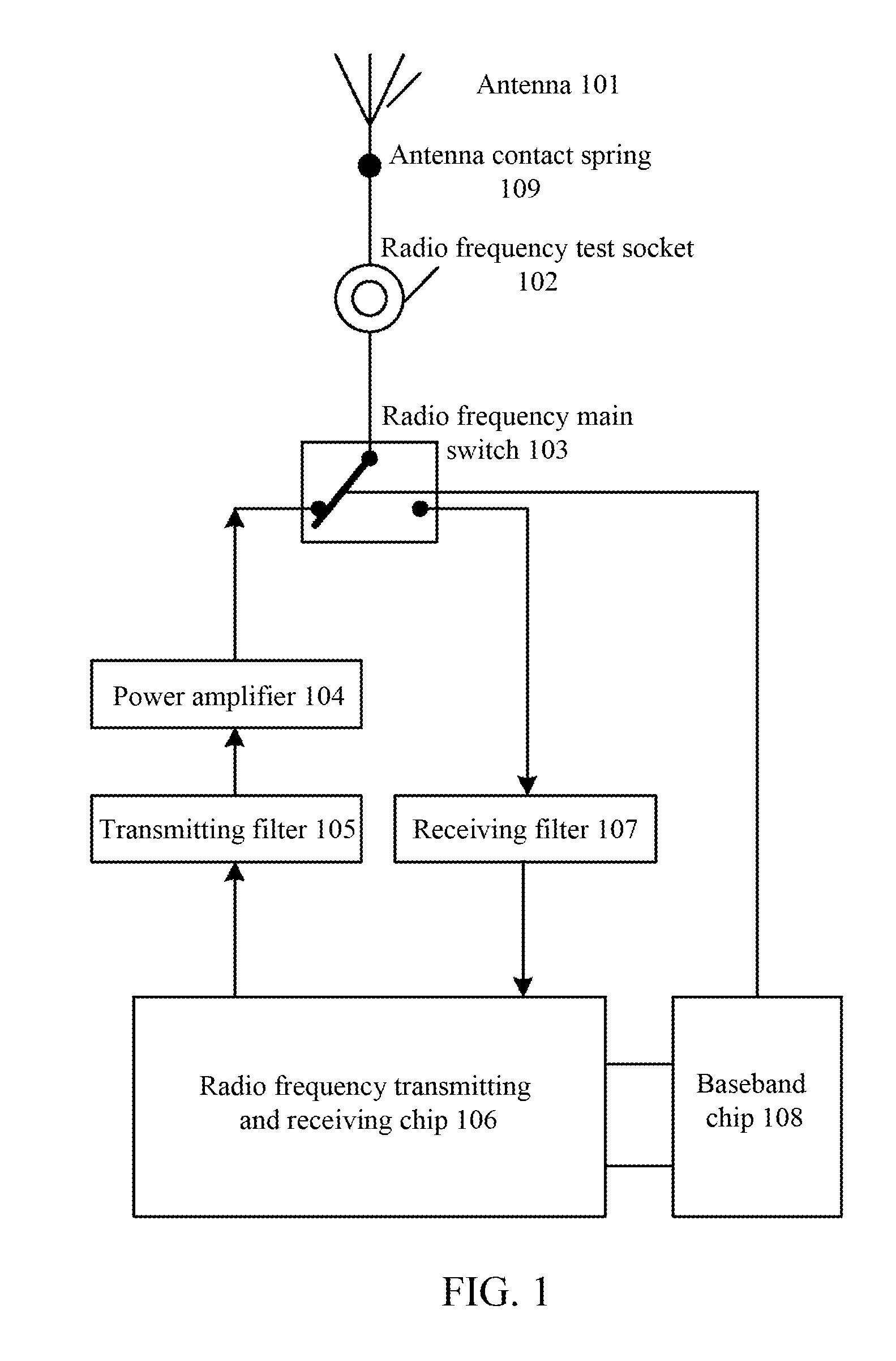
[0057]FIG. 1 shows a component structure of a radio frequency link for a TD-LTE mode. As shown in FIG. 1, the radio frequency link includes a radio frequency transmitting link and a radio frequency receiving link.

[0058]The radio frequency transmitting link includes a baseband chip 108, a radio frequency transmitting and receiving chip 106, a transmitting filter 105, a power amplifier 104, a radio frequency main switch 103, a radio frequency test socket 102, an antenna contact spring 109 and the antenna 101. When a signal is transmitted, the radio frequency transmitting and receiving chip 106 modulates a baseband signal output by the baseband chip 108 to a high-frequency carrier signal and transmits the high-frequency carrier signal to the transmitting filter 105. The transmitting filter 105 filters the received high-frequency carrier signal and then transmits the high-frequency carrier signal to the power amplifier 104. The power amplifier 104 amplifies the received high-frequency c...


PUM


Abstract

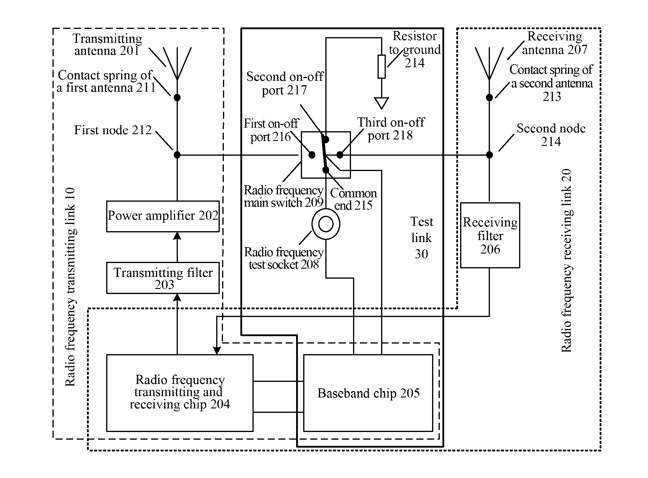
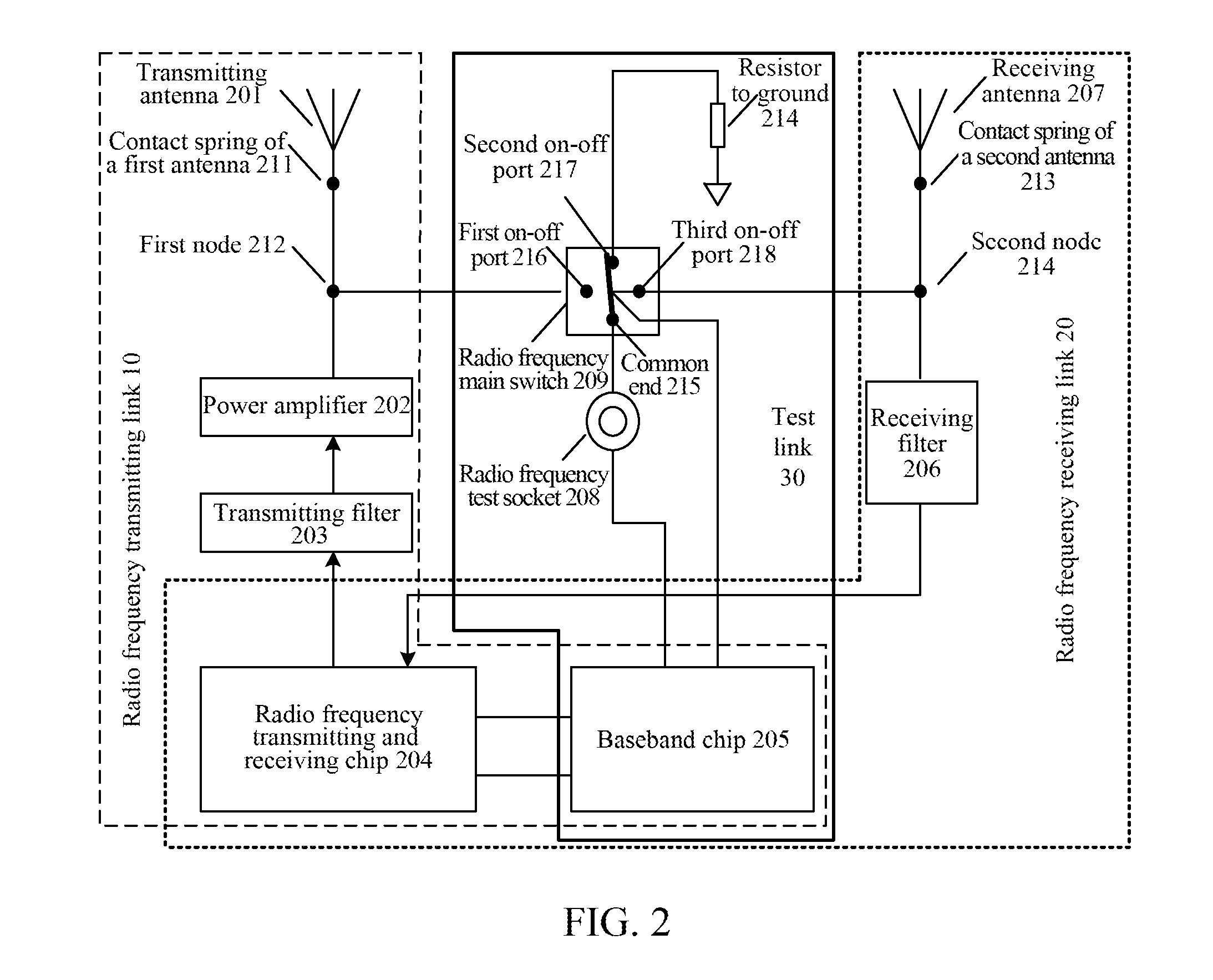
The present document discloses a device for improving receiving and transmitting performance of radio frequency link, comprising a radio frequency transmitting link, a radio frequency receiving link and a test link, wherein a first node is set between a power amplifier and a contact spring of first antenna in the radio frequency transmitting link, the first node is connected to a first on-off port of a radio frequency main switch in the test link; a second node is set between a receiving filter and a contact spring of second antenna in the radio frequency receiving link, the second node is connected to a third on-off port of the radio frequency main switch in the test link; and a second on-off port of the radio frequency main switch in the test link is connected to ground via a resistor.

Description

CROSS-REFERENCE TO RELATED APPLICATION(S)[0001]This application is the U.S. National Phase application of PCT application number PCT / CN2014 / 082348 having a PCT filing date of Jul. 16, 2014, which claims priority of Chinese patent application 201310733353.8 filed on Dec. 26, 2013, the disclosures of which are hereby incorporated by reference.TECHNICAL FIELD[0002]The present invention relates to performance management technology of radio frequency links in a mobile terminal, in particular to a device, a mobile terminal, a method and a storage medium for improving receiving and transmitting performance of a radio frequency link.BACKGROUND OF RELATED ART[0003]With the high-speed development and deep popularization of wireless communication technology, users have already been able to deeply feel wireless mobile life styles brought by high speed and convenience of high technology. Mobile terminal products such as function phones, smart phones, data cards and portable WiFi hot spots orient...

Claims


Application Information

Patent Timeline
IPC IPC(8): H04B17/00
CPCH04B17/0085
Inventor WANG, ZHENYUZHANG, CHENGZANLAI, YUQIANG
Owner ZTE CORP
Learn More