
An autonomous detecting and positioning method of indoor wireless network faults

Active Publication Date: 2016-11-03
RANPLAN WIRELESS NETWORK DESIGN
View PDF0 Cites 18 Cited by
  • Summary
  • Abstract
  • Description
  • Claims
  • Application Information

AI Technical Summary

Benefits of technology

This patent proposes a method for accurately positioning network faults by using dial testing mobile phones. This method requires no additional human or resource costs, as it does not require measuring on site or constructing additional wireless networks. It uses a ray-tracing propagation model to predict signal strength and selects key testing positions based on signal strength to minimize the impact of antenna changes. The method can autonomously detect network faults and replace wireless network devices with similar index, reducing the impact of room separators. The key technical effects are accurate positioning of network faults and reduced human and resource costs.

Problems solved by technology

On the one hand, this is due to the late starting of indoor networks relative to outdoor networks, on the other hand, this is also because that it is harder to monitor indoor passive devices, and a simple but effective monitor way is also lacked.
The frequently employed methods to monitor faults of indoor wireless networks mainly include artificial dial testing and periodic inspection, which not only takes a long period of time to inspect, but also cannot discover and locate the faults in time.
However, although this method is reliable, it needs to build an additional wireless sensor network which costs a lot.
In conclusion, at present, a technical problem that needs to be solved urgently by persons skilled in the art is: how to achieve automatic detection and rapid positioning of indoor wireless network faults.

Method used


Image

  • An autonomous detecting and positioning method of indoor wireless network faults
  • An autonomous detecting and positioning method of indoor wireless network faults
  • An autonomous detecting and positioning method of indoor wireless network faults

Examples


Embodiment Construction

[0046]The present invention will be further described in combination with the figures and embodiment.

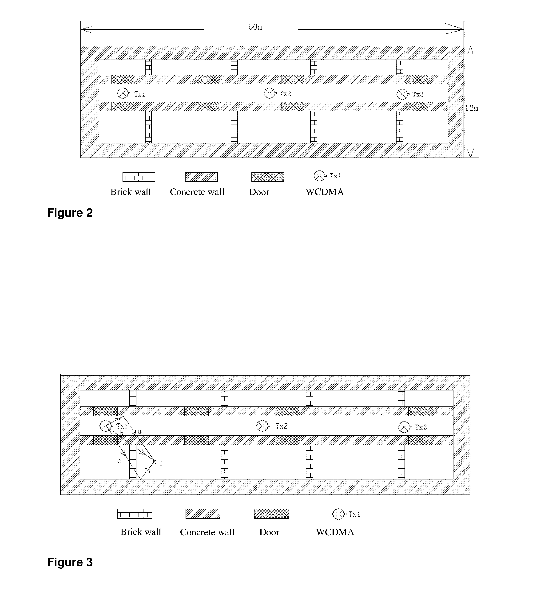
[0047]An autonomous detecting and positioning method of indoor wireless network faults of this invention is applied to autonomously detect and position the faults of the WCDMA indoor wireless network in a target building of 5 floors (the floorage of each floor is 600 m2). The WCDMA indoor wireless networks in the target building belong to a same cell, and have 15 indoor wireless network transmitting antennas in total, 3 for each floor, which are arranged above the 2.4 meters high ceilings.

[0048]The technical solution this invention is not limited to WCDMA networks, but can also be applied to one or a combination of multiple other wireless communication networks (wireless wide area network and wireless local network).

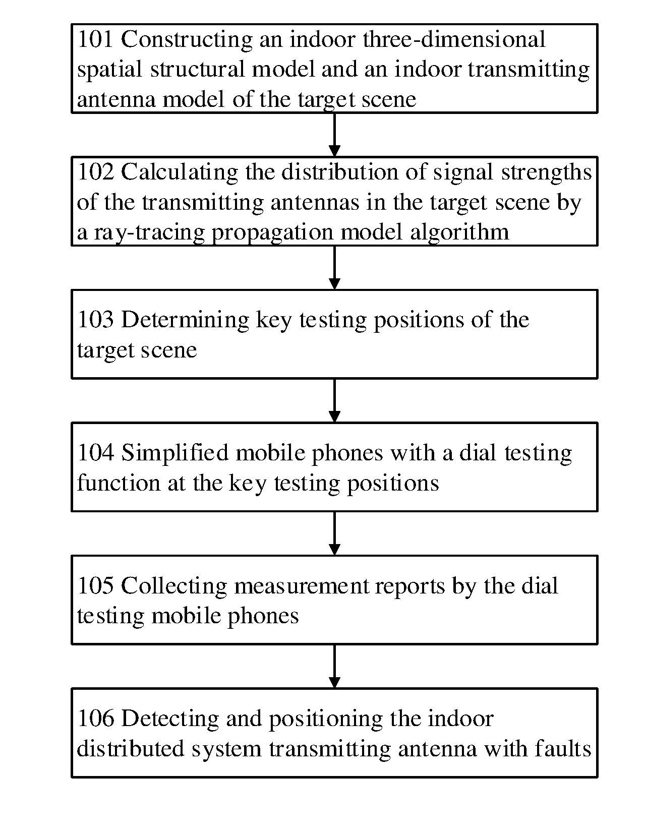
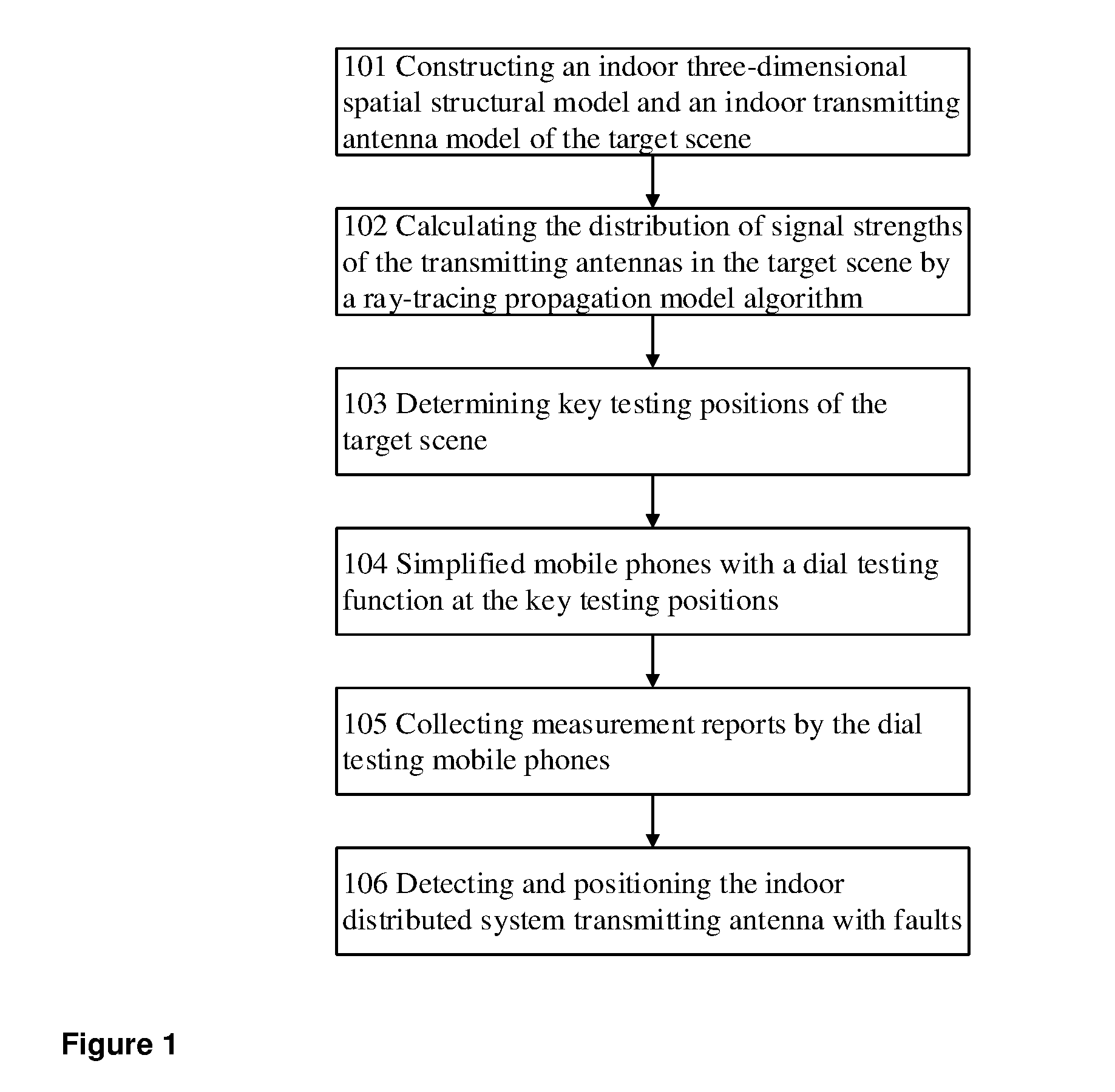
[0049]As shown in FIG. 1, a method of rapidly establishing fingerprint database of indoor wireless signals comprises the following steps:

[0050](1): 101—building an indoor...


PUM


Abstract

Method of autonomous detection and positioning method of indoor wireless network faults, the method comprising: building an indoor three-dimensional spatial structural model and an indoor transmitting antenna model of a target building, calculating the signal strength of the indoor transmitting antenna model inside the target building according to a ray-tracing propagation model algorithm to determine key testing positions of the target building, each key test position being associated to an individual transmitting antenna and maximizing the difference between the signal strength generated by its corresponding antenna and that generated by other antennas, deploying mobile phones with an automatic dial testing function at the key testing positions of indoor wireless networks and starting the dial testing mobile phones when the wireless networks are idle, collecting measurement reports reported by the dial testing mobile phones, detecting and locating faults of indoor networks and devices according to the measurement reports.

Description

FIELD OF THE INVENTION[0001]The present invention relates to an autonomous detecting and positioning method of indoor wireless network faults, which belongs to the field of indoor wireless network maintenance of mobile communication field.BACKGROUND OF THE INVENTION[0002]With the development of wireless communication technology and the increase of indoor data business, indoor wireless signal becomes more and more important, and indoor wireless networks become one of the principle ways to deal with indoor network coverage and shunt, or accept, the user's traffic flow. Therefore, to detect the faults of indoor wireless network devices in time is the premise of ensuring normal operations of the existing wireless communication networks and improving customer satisfaction. Under the current situation, the monitor rate of mobile operators on outdoor active devices can reach above 90%, while the monitor on passive devices of indoor wireless networks is just on its debut. On the one hand, t...

Claims


Application Information

Patent Timeline
IPC IPC(8): H04W24/06H04B17/318H04W64/00
CPCH04W24/06H04B17/318H04W64/003H04W84/10H04W16/225H04W64/00H04W16/20
Inventor ZHANG, JIESONG, HUIQIN, CHUNXIA
Owner RANPLAN WIRELESS NETWORK DESIGN
Learn More