
Method for the continuous thermal hydrolysis of sludge with a high dryness value

a technology of thermal hydrolysis and sludge, which is applied in the direction of water/sludge/sewage treatment, water treatment pressure conditions, specific water treatment objectives, etc., can solve the problems of low potential energy recovery potential of the mode of operation, poor degradability of certain organic compounds by biological means, premature wear and tear, etc., to reduce the viscosity of de-structured sludge and save energy implementing to make the rotor operate.

Active Publication Date: 2016-11-10
VEOLIA WATER SOLUTIONS & TECH SUPPORT
View PDF4 Cites 3 Cited by
  • Summary
  • Abstract
  • Description
  • Claims
  • Application Information

AI Technical Summary

Benefits of technology

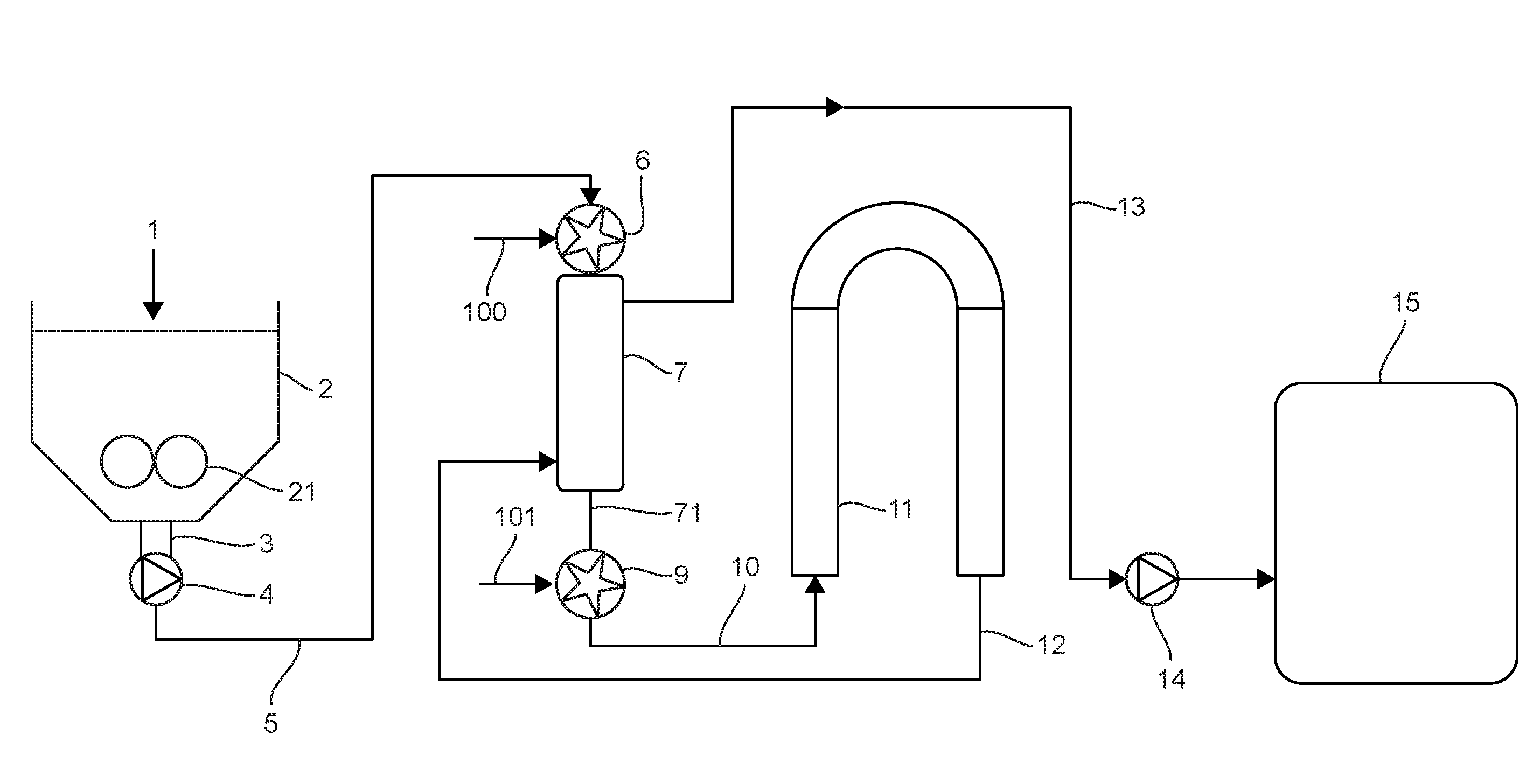
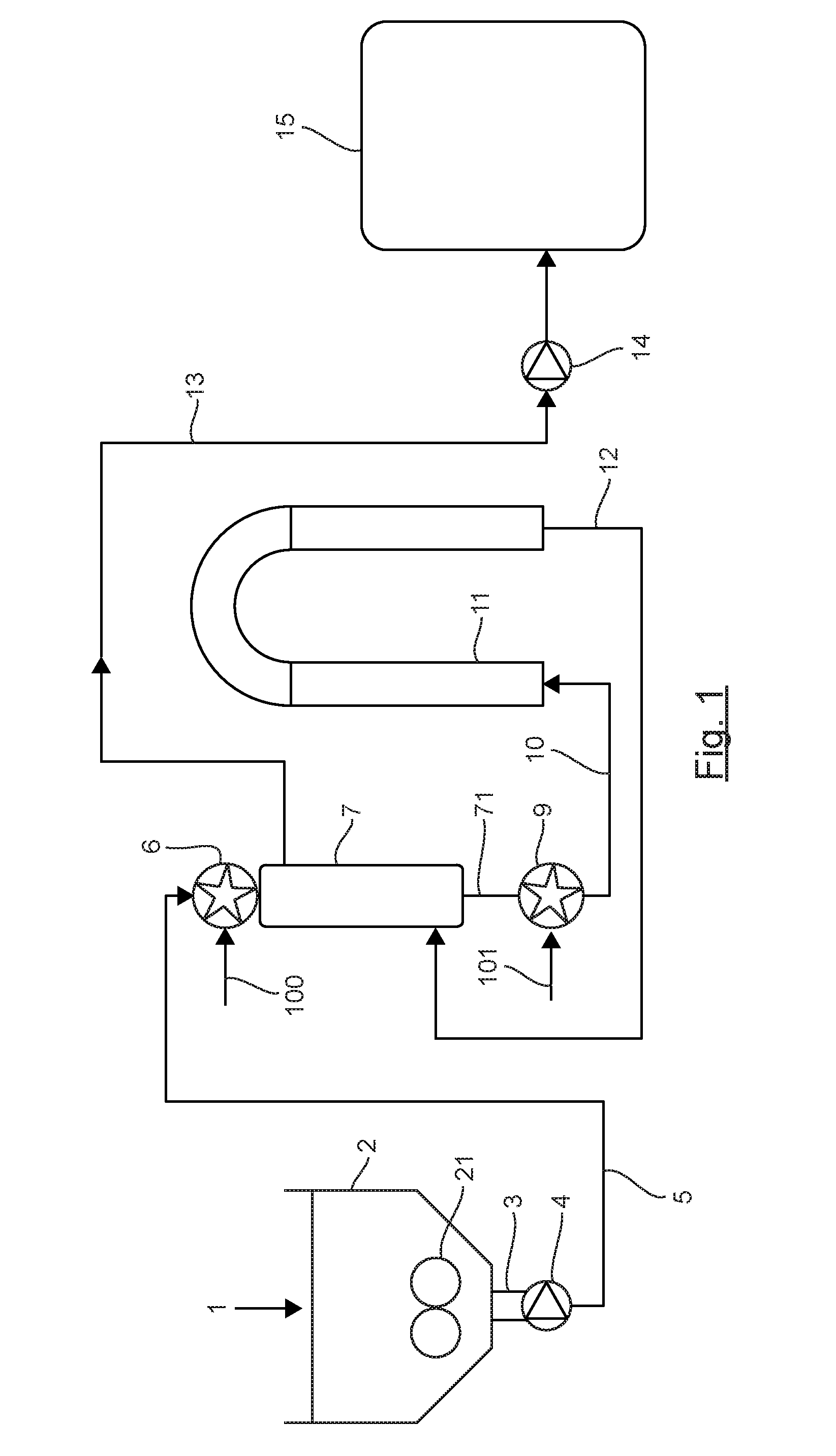
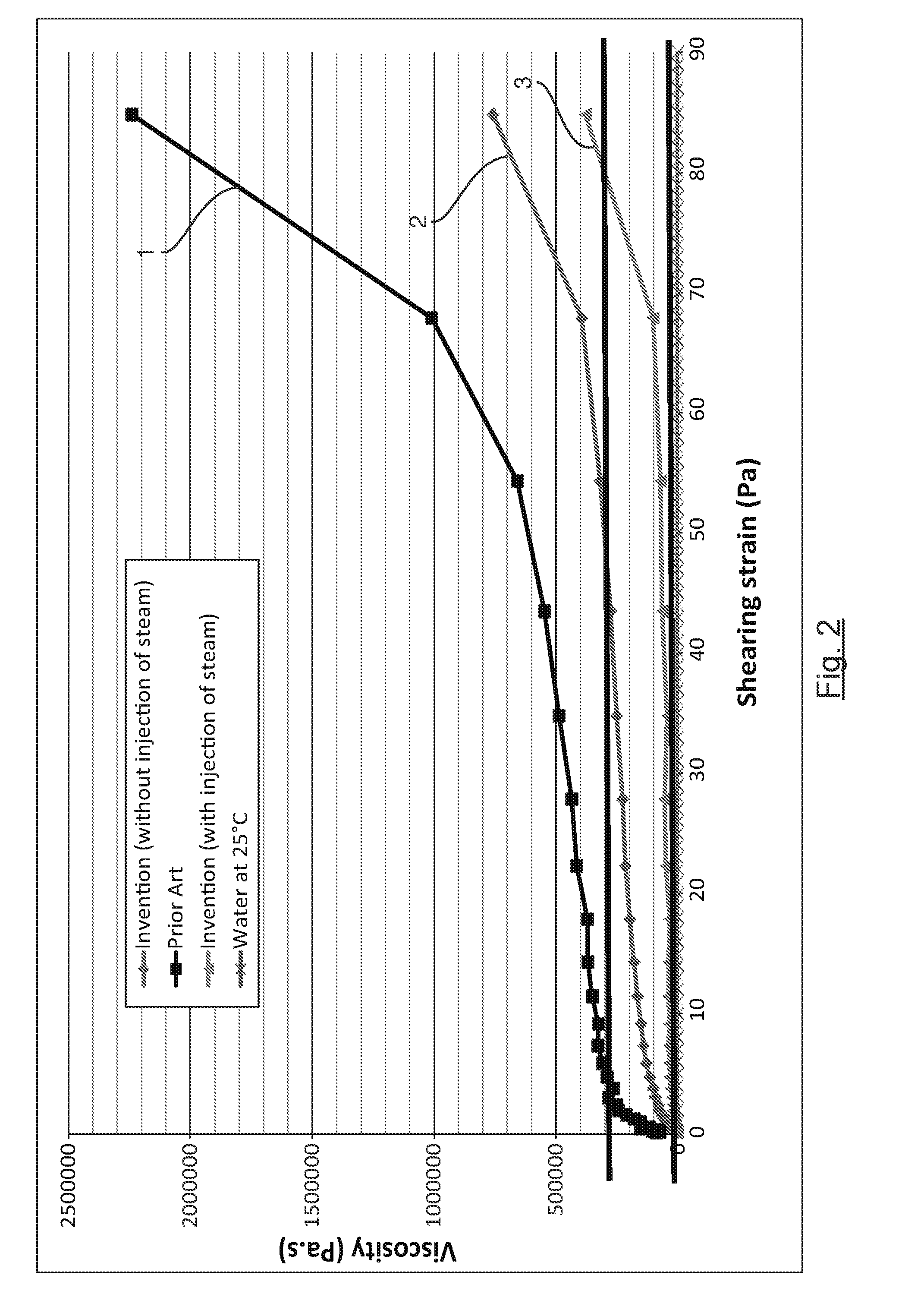
This patent is about a method for increasing the fluidity of sludge to be treated using thermal hydrolysis. The method involves subjecting the sludge to a high speed gradient in a dynamic mixer and heating it to recover heat from the sludge without using any intermediate fluid. The invention is based on the belief that subjecting the sludge to a high shear strain breaks its structure and lowers its viscosity, which further fluidizes it. The combination of mechanical de-structuring and heating the sludge further enhances its fluidity. The heat exchanger in the invention can extend vertically or horizontally, with the latter being more efficient in terms of homogeneity of flow and reducing footprint.

Problems solved by technology

However, certain organic compounds are poorly degradable by biological means.
Such batch methods have the drawbacks of requiring the management of cycles for treating different batches of sludge that have to be treated and a repetitive operation of certain apparatuses such as the opening / closing of valves for example, which can lead to premature wear and tear.
Above all, this mode of operation has low potential for energy recovery.
In practice, the management of the exchangers proves to be difficult and entails constraints for the user since they require periods of stoppage for maintenance and cleaning.
In addition, this configuration is limited in terms of concentration of sludge to be treated inasmuch as they cannot be used to treatment sludge having a dry content of over 10%.
However, although it has considerably improved the treatment of sludge by thermal hydrolysis as compared with other methods existing in the market, it nevertheless has certain drawbacks.
Indeed, if the dry content of the sludge to be hydrolyzed introduced into the reactor is too high, then it can prove to be difficult to inject steam into this sludge.
Beyond certain levels of dry content, the thermal hydrolysis can be incomplete, limiting the performance of the anerobic digestion planned downstream to this hydrolysis.
The methods of thermal hydrolysis on sludge having high dry content therefore come up against the difficulty of efficiently carrying out the injection of steam into this sludge as well as the mixing of this sludge with the injected steam.
The methods of continuous thermal hydrolysis do not make it possible, at present, to optimize their energy consumption because conventional heat exchangers are not designed to treat pasty fluids such as sludge.
Thus, in practice, it is not possible to envisage the use of such exchangers to recover heat from hydrolyzed sludge.
However, while these exchangers can theoretically work with sludge having a dry content of over 10%, they are in practice limited to dry content values of 8% to 10%.
Another considerable drawback of scraped surface exchangers is that they require an intermediate fluid, generally water, to heat the incoming sludge or cool the outgoing sludge.
Beyond the maximum dry content limit of 10%, the pressure losses observed, of the order of a few bars depending on the dry content of the sludge to be treated, and the difficulties of operation of the exchanger, make the method economically unpromising.
Another drawback is that these exchangers are also limited in capacity: it is therefore necessary to place several exchangers in series in order to treat a sufficient volume.
As a consequence, the energy consumption of motors that drive the exchangers gets added up and this entails penalties in terms of energy consumption.
Another disadvantage of these scraping shaft exchangers or exchangers using additional mechanical means is related to their maintenance.
The fouling related to the circulation of pasty sludge requires regular maintenance, which is difficult to implement.

Method used


Image

  • Method for the continuous thermal hydrolysis of sludge with a high dryness value
  • Method for the continuous thermal hydrolysis of sludge with a high dryness value
  • Method for the continuous thermal hydrolysis of sludge with a high dryness value

Examples


Embodiment Construction

[0056]The general principle of the invention relies on the implementing of a step for the de-structuring of the sludge followed by a step for heating the sludge in a heat exchanger, upstream to a method of thermal hydrolysis. The step for de-structuring the sludge is done by subjecting the sludge to a high-speed gradient, enabling its structure to be broken, possibly accompanied by pre-heating through the injection of steam. The sludge thus de-structured and possibly heated can enter the heat exchanger where it will be heated through the recovery of heat from the hydrolyzed sludge. The heating of the de-structured sludge, whether pre-heated or not, reduces its viscosity thus enabling the sludge to be made to circulate in the heat exchanger while considerably reducing or even totally eliminating the pressure losses within the exchanger. The sludge thus de-structured flows more easily within the heat exchangers, and the pressure losses are considerably reduced. In addition, the exchan...


PUM


Abstract

Method and plant to implement the continuous thermal hydrolysis of sludge to be treated containing organic matter, the method comprising at least:a. a step for de-structuring said sludge to be treated producing de-structured sludge;b. a step for the thermal hydrolysis of said de-structured sludge within a thermal hydrolysis reactor producing hydrolyzed sludge;c. a step for cooling said hydrolyzed sludge; said step for de-structuring consisting in:introducing said sludge to be treated into a dynamic mixer;heating said sludge coming from said dynamic mixer, this heating being obtained by the introduction, into a heat exchanger, on the one hand of said sludge coming from said dynamic mixer and, on the other hand, of said hydrolyzed sludge, this introduction inducing said cooling.

Description

FIELD OF THE INVENTION[0001]The field of the invention is that of the treatment of sludge containing organic matter such as sludge from cleansing stations. More specifically, the method relates to a method for the continuous thermal hydrolysis of sludge containing organic matter, mixed or not mixed with other wastes containing organic matter. This sludge or these wastes can come for example from the treatment of domestic wastewater (for example digested or non-digested sludge coming from cleansing stations, fats from pre-treatment processes, etc.) or it can come from the treatment of industrial wastewater (for example wastewater coming from the agro-food industry, effluent from slaughterhouses, molasses, etc.), or it can be constituted by discharged matter from grease tanks. The term “sludge” shall be used hereafter to designate this sludge and / or these wastes.PRIOR ART[0002]Sludge coming from the treatment of wastewater, whether domestic or industrial, can be treated biologically, ...

Claims


Application Information

Patent Timeline
IPC IPC(8): C02F11/18C02F1/02
CPCC02F11/18C02F2301/06C02F2303/06C02F1/025C02F1/34
Inventor CRAMPON, CEDRICCHAUZY, JULIENDJAFER, MALIK
Owner VEOLIA WATER SOLUTIONS & TECH SUPPORT
Learn More