High bandwidth rogowski transducer with screened coil

a transducer and high-bandwidth technology, applied in the direction of transformer/inductance coil/winding/connection, instrument screening arrangement, transformer/inductance coil/winding/connection, etc., to achieve the effect of high bandwidth, fast current change, and high bandwidth

Active Publication Date: 2016-11-10
POWER ELECTRONICS MEASUREMENTS
View PDF1 Cites 11 Cited by
  • Summary
  • Abstract
  • Description
  • Claims
  • Application Information

AI Technical Summary

Benefits of technology

[0016]To enable Rogowski transducers to be used for current measurement in power electronic equipment the Rogowski coil is preferably thin (i.e. having a small cross-section diameter) so that it can be inserted in geometrically cramped situations and furthermore that the Rogowski device has a high bandwidth to measure very fast current changes. This imposes constraints on the coil design and it is an objective of this invention to provide a Rogowski coil design which achieves the required screening whist at the same time providing a high bandwidth for the current measurement.
[0020]The inventor has identified that the above-stated disadvantage can be addressed by using two separate screens: an outer screen for by-passing the interference current to ground and an inner screen for acting as the coil return path. Although this adds to the complexity and cost of the coil, it gives several advantages. Not only does the double screening reduce the interference but also the screens do not both have to be connected to the input of the integrator.

Problems solved by technology

The inventor has appreciated that a disadvantage lies in using the screen for the dual purpose of being the return conductor for the signal as well as being the path to ground for the interference current.

Method used


Image

  • High bandwidth rogowski transducer with screened coil
  • High bandwidth rogowski transducer with screened coil
  • High bandwidth rogowski transducer with screened coil

Examples


Embodiment Construction

[0047]While the specification concludes with claims defining the features of the invention that are regarded as novel, it is believed that the invention will be better understood from a consideration of the following description in conjunction with the drawing figures, in which like reference numerals are carried forward. It is to be understood that the disclosed embodiments are merely exemplary of the invention, which can be embodied in various forms.

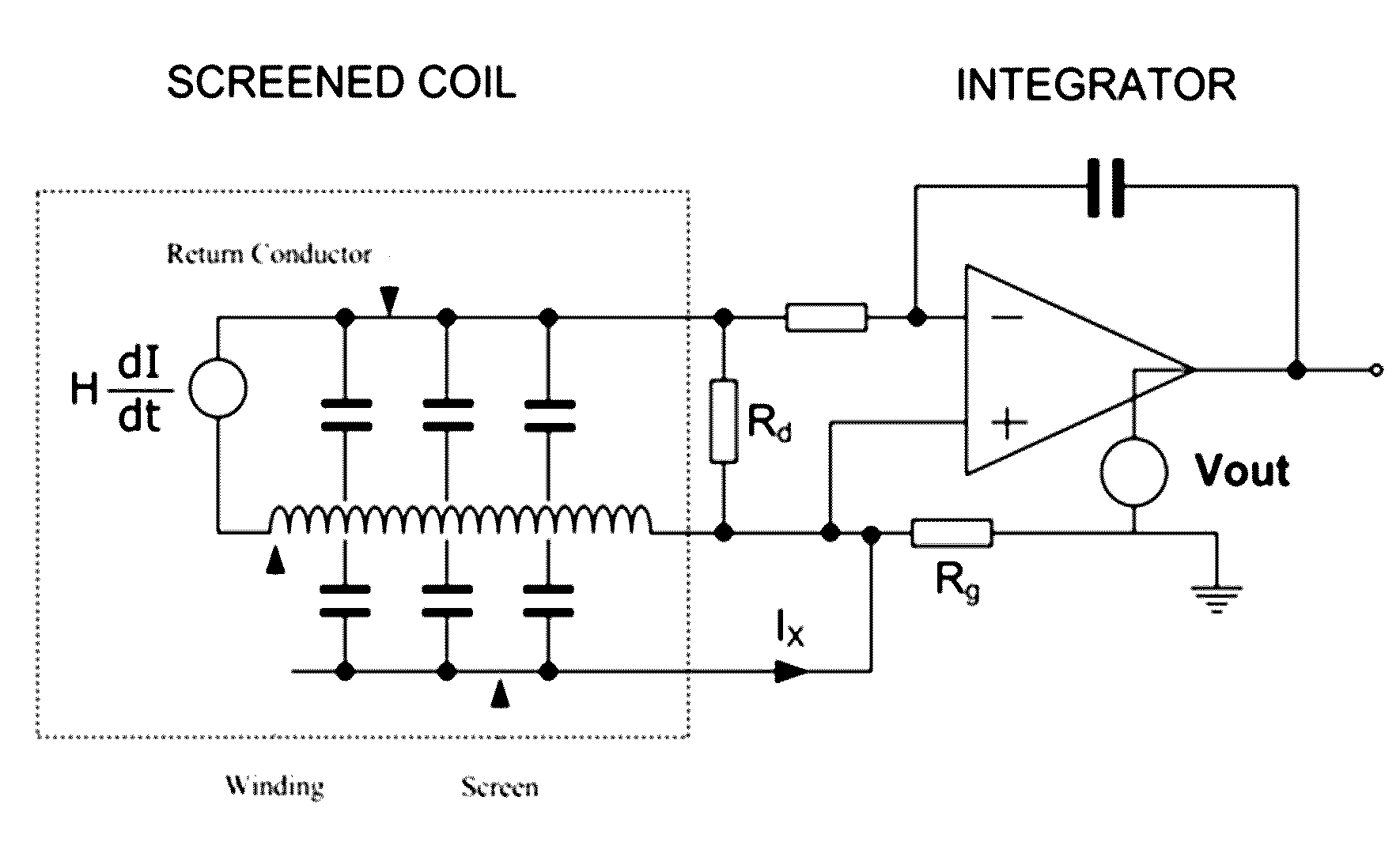
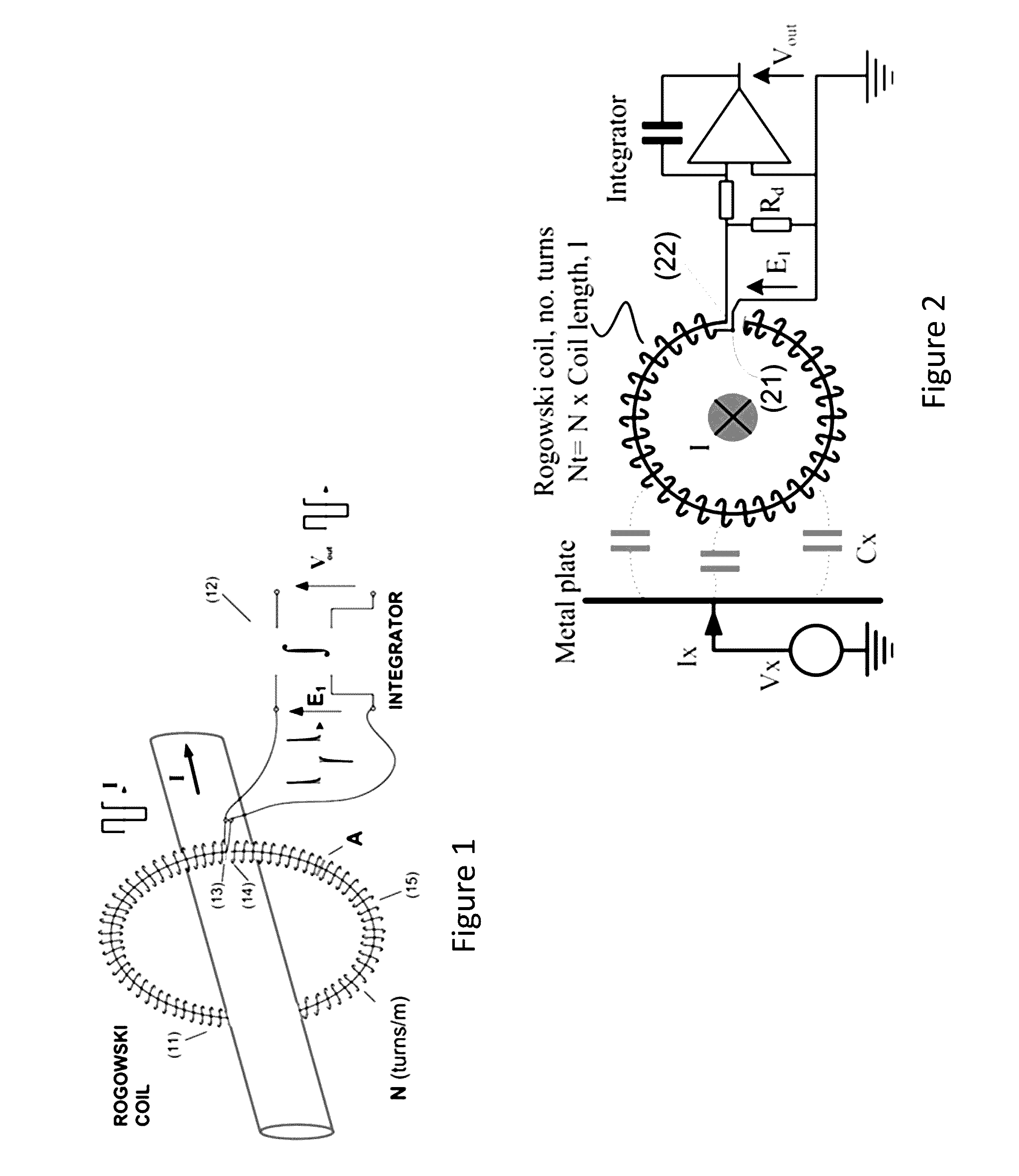
[0048]FIG. 1 shows schematically a Rogowski transducer comprising a Rogowski coil and an electrical integrator. The coil 11 is wound on a plastic former. The former is toroidal, with a circular cross-section, forming a ring torus. The toroidal loop of the former has an opening and is thereby arranged to form an openable and closable loop. When the coil 11 is wound on the former, this is referred to as a “clip-around” coil. The loop of the former can be opened in order for the loop to enclose or surround a conductor passing through the ...


PUM

PropertyMeasurementUnit
electrically conductiveaaaaaaaaaa
currentaaaaaaaaaa
conductiveaaaaaaaaaa

Abstract

A current measuring device is disclosed, comprising: an electrically conductive coil having a first end and a second end; a first screen surrounding the coil and arranged to provide a current path from the second end of the coil to a location proximal to the first end of the coil; and a second screen surrounding the first screen and the coil.

Description

FIELD OF THE INVENTION[0001]This disclosure relates to current measuring devices using a Rogowski coil. It relates in particular to the fitting of one or more electrostatic screens or shields around the coil to prevent interference with the current measurement due to high frequency voltages or voltage transients on conductors in close proximity to the coil.[0002]The principle of operation of Rogowski transducers is well known. Details of the design and operation of Rogowski transducers can be found for example in “Wide bandwidth Rogowski current transducers—Part 1: The Rogowski Coil” European Power Electronics Journal Vol 3 No 1 Mar. 1993 pp 51-59 by W F Ray & R M Davis and in “Wide bandwidth Rogowski current transducers Part 2: The Integrator” European Power Electronics Journal Vol 3 No 2 Jun. 1993 pp 116-122, by W F Ray.[0003]In general terms a Rogowski transducer comprises a Rogowski coil and an integrator. A Rogowski coil is a coil having a substantially uniform turns density of...

Claims


Application Information

Patent Timeline
Patent Type & Authority Applications(United States)
IPC IPC(8): G01R15/18H01F27/28
CPCH01F27/2885G01R15/181G01R1/18G01R19/0092
Inventor HEWSON, CHRISTOPHER RENE
Owner POWER ELECTRONICS MEASUREMENTS
Why Eureka
Try Eureka