Supercharge Your Innovation With Domain-Expert AI Agents!

Reticle Shape Correction Apparatus and Photolithography Tool Using Same

a technology of reticle and tool, which is applied in the field of integrated circuit (ic) fabrication, can solve the problems of increasing the structural complexity of the objective, posing a great challenge to image quality guarantee, and a large number of additions, so as to reduce the weight load of the reticle, improve the exposure efficiency, and prevent the effect of gravitational deformation

Active Publication Date: 2016-11-10
SHANGHAI MICRO ELECTRONICS EQUIP (GRP) CO LTD
View PDF4 Cites 2 Cited by
  • Summary
  • Abstract
  • Description
  • Claims
  • Application Information

AI Technical Summary

Benefits of technology

The invention offers the following benefits over previous techniques: the suckers don't block the view of the reticle, allowing for better exposure efficiency; they reduce the weight of the reticle and prevent deformation from gravity; and the apparatus is independent from other components of the photolithography tool, reducing vibration and noise.

Problems solved by technology

However, the great impact of reticle warpage on exposure accuracy, in particular, on the focal-depth range of an objective, poses a great challenge to image quality guaranteeing.
However, this leads to increases in structural complexity of the objective and the addition of a considerable number of movable members, which are not conducive to the reliability of photolithography equipment.
However, the presence of the glass plate affects the performance of the illumination system in exposing the reticle.
Moreover, the glass plate itself also experiences deformation caused by its own gravity, which further deteriorates the exposure performance.
Further, the reticle, the glass plate and the pneumatic device are arranged on the same frame, which increases vibration and a weight load of the reticle.

Method used


Image

  • Reticle Shape Correction Apparatus and Photolithography Tool Using Same
  • Reticle Shape Correction Apparatus and Photolithography Tool Using Same
  • Reticle Shape Correction Apparatus and Photolithography Tool Using Same

Examples


Embodiment Construction

[0034]The above purposes, features and advantages of the present invention will become more apparent from the following description of several specific embodiments of the invention, which is to be read in connection with the accompanying drawings. It is noted that the drawings are provided in a very simplified form not necessarily presented to scale, with the only purpose for convenience and clarity in explaining the embodiments.

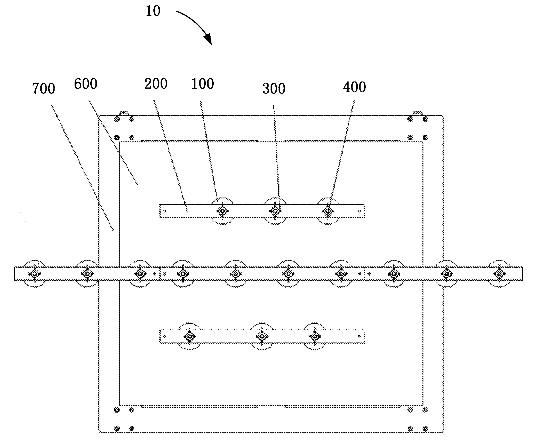
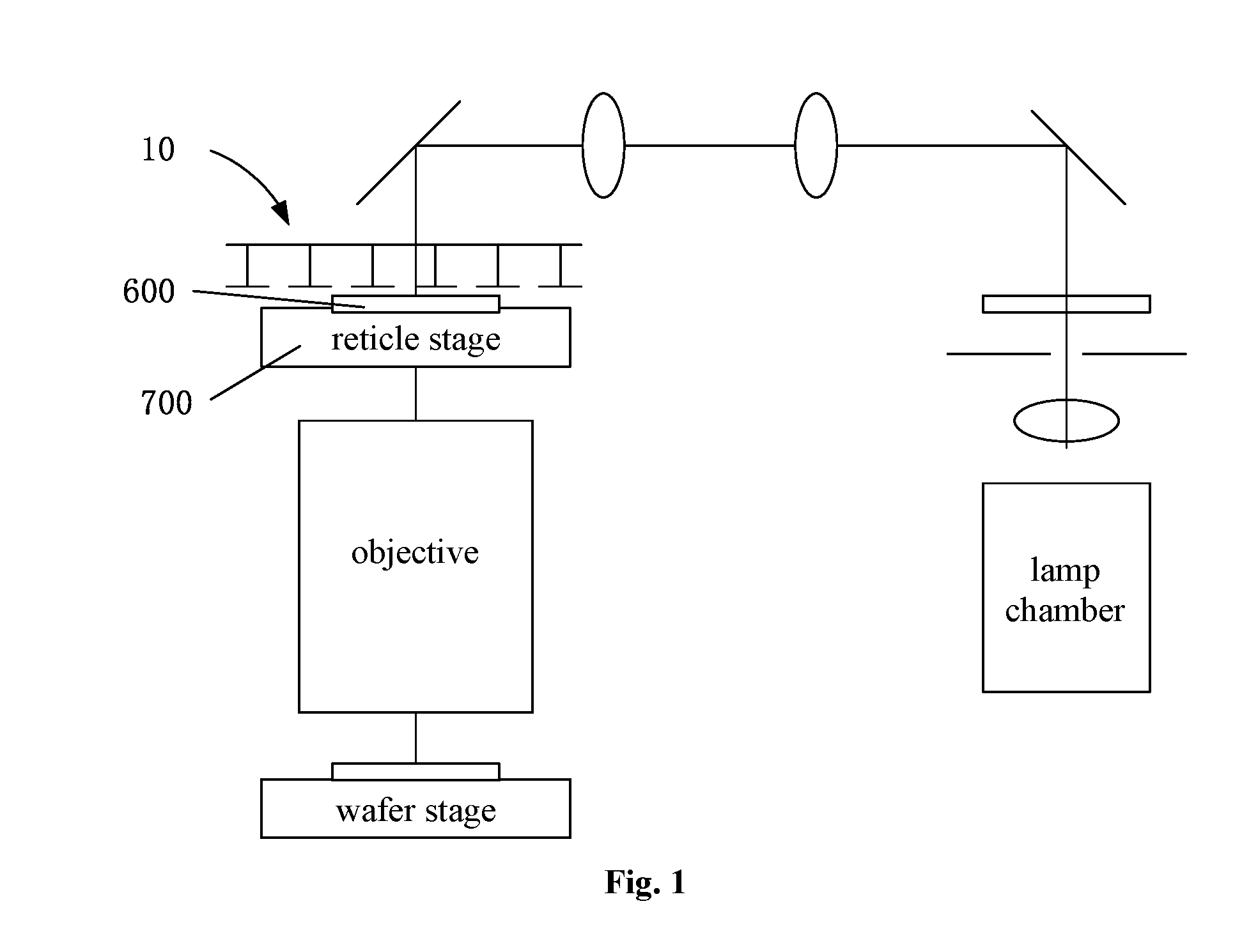
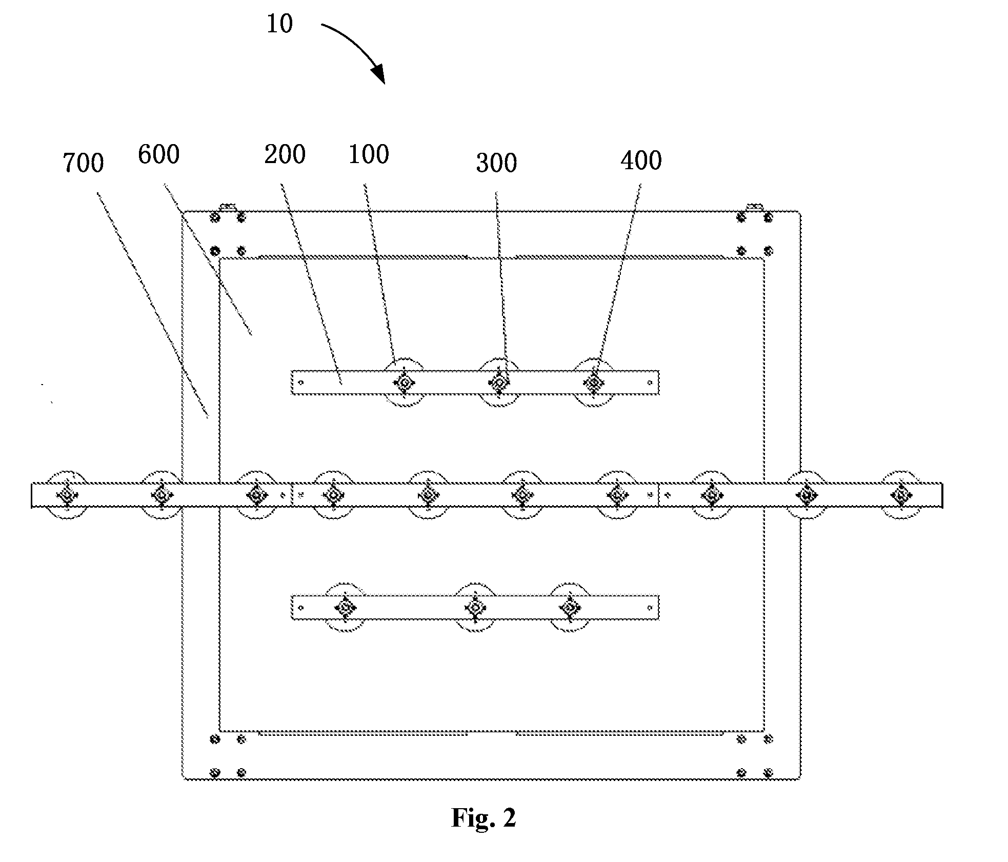
[0035]As shown in FIGS. 1 to 3, an apparatus 10 for correcting the shape of a reticle according to the present invention includes suckers 100, sucker mounting frames 200 and pneumatic control systems (not shown in the figures). The sucker mounting frames 200 are disposed above a reticle stage 700, and the suckers 100 are mounted on the bottoms of the sucker mounting frames 200 in such a manner that they are spaced apart from one another and correspond to areas out of trapezoidal exposure fields of view (FOVs) 610 (FIGS. 6 and 7) on the reticle 600. The pneum...


PUM


Abstract

An apparatus for correcting the shape of a reticle, including: suckers; a sucker mounting frame; and a pneumatic control system, wherein the sucker mounting frame is disposed above a reticle stage, the suckers are mounted on a bottom of the sucker mounting frame in a manner of being spaced apart from one another; and the pneumatic control system is configured to control the suckers to retain the reticle by suction or to release the reticle. The suckers are so arranged that they do not block trapezoidal exposure fields of view on the reticle, thereby allowing a light beam to be fully (100%) incident on the reticle, which results in improved exposure efficiency. The apparatus is mounted separately from a photolithography tool by which it is employed, enabling a lower weight load on the reticle. Additionally, the apparatus is not in contact with any component disposed in the photolithography tool and will not introduce additional external vibration to the tool.

Description

TECHNICAL FIELD[0001]The present invention relates to the field of integrated circuit (IC) fabrication and, more particularly, to an apparatus for correcting the shape of a reticle. The invention is also directed to a photolithography tool using the apparatus.BACKGROUND[0002]With increasing enlargement of thin-film transistor (TFT) substrates, the size of reticles used in photolithography equipment for TFT fabrication is accordingly increasing, from the initial 6 inches to 920 mm×800 mm for 5.5th generation (G5.5) photolithography equipment and up to 1320 mm×1108 mm for 8.5th generation (G8.5) reticles. When such a huge reticle is retained on a reticle stage by suction, its downward bending due to gravity is inevitable, which can be as great as up to over 40 μm. For TFT-fabricating photolithography equipment of the 5.5th or more recent generations, the use of field-of-view (FOV) stitching or ultra-large FOV techniques has become an irresistible trend. However, the great impact of re...

Claims


Application Information

Patent Timeline
IPC IPC(8): G03F7/20
CPCG03F7/70741H01L21/6838G03F7/707G03F7/70783G03F1/70G03F7/20G03F7/70775
Inventor LI, LINGYULI, YULONG
Owner SHANGHAI MICRO ELECTRONICS EQUIP (GRP) CO LTD
Features
  • R&D
  • Intellectual Property
  • Life Sciences
  • Materials
  • Tech Scout
  • Unparalleled Data Quality
  • Higher Quality Content
  • 60% Fewer Hallucinations
Learn More