Light source module unit for exposure and exposure device having light source module unit

A light source module and light source technology, which is applied in the field of light sources for exposure, can solve the problems of ultra-high definition and limitations in the core technology of the display industry that cannot realize the miniaturization of exposure patterns, achieve high resolution, reduce light source replacement costs, and achieve high resolution. Effect

Active Publication Date: 2018-04-17
赵南稙
View PDF3 Cites 2 Cited by
  • Summary
  • Abstract
  • Description
  • Claims
  • Application Information

AI Technical Summary

Problems solved by technology

[0005] However, despite this, due to the technical limitations of the miniaturization process of the exposure pattern using the existing exposure light source (Hg Lamp, mercury lamp), it is a pity that the miniaturization of the exposure pattern and the core technology of the display industry cannot be realized. ultra hd
[0006] In addition, due to the recent trend of miniaturization, increase in capacity, and high integration and high density of semiconductor elements, there is an increasing demand for miniaturization and high precision of exposure patterns. Existing light sources for exposure have limitations in meeting the current requirements for miniaturized patterns

Method used


Image

  • Light source module unit for exposure and exposure device having light source module unit
  • Light source module unit for exposure and exposure device having light source module unit
  • Light source module unit for exposure and exposure device having light source module unit

Examples


Embodiment Construction

[0039] Hereinafter, the light source module unit for exposure according to the present invention will be described in detail with reference to the drawings. The content described below and the accompanying drawings are merely descriptions based on preferred embodiments of the present invention, and do not limit the light source module unit for exposure of the present invention described in the claims.

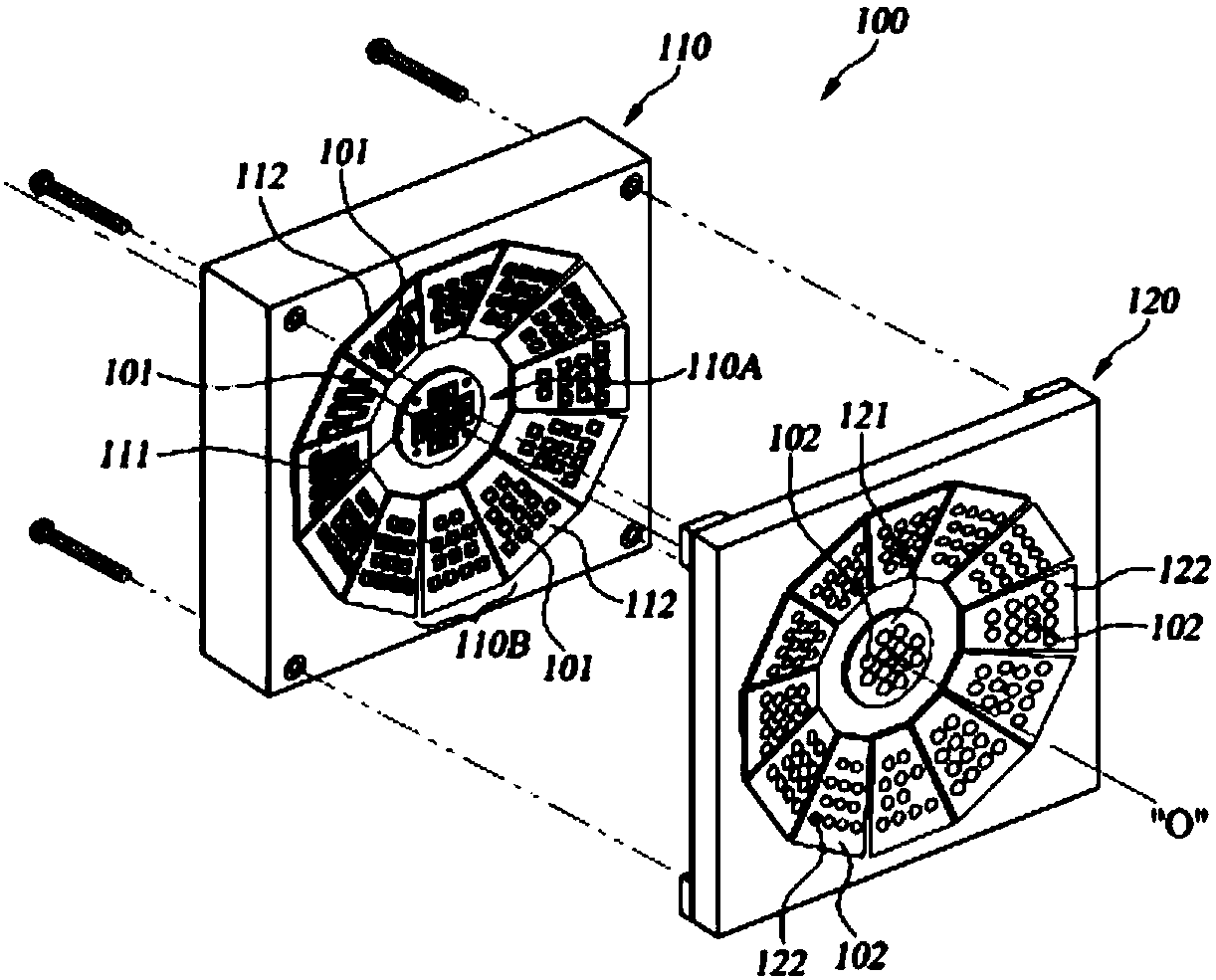
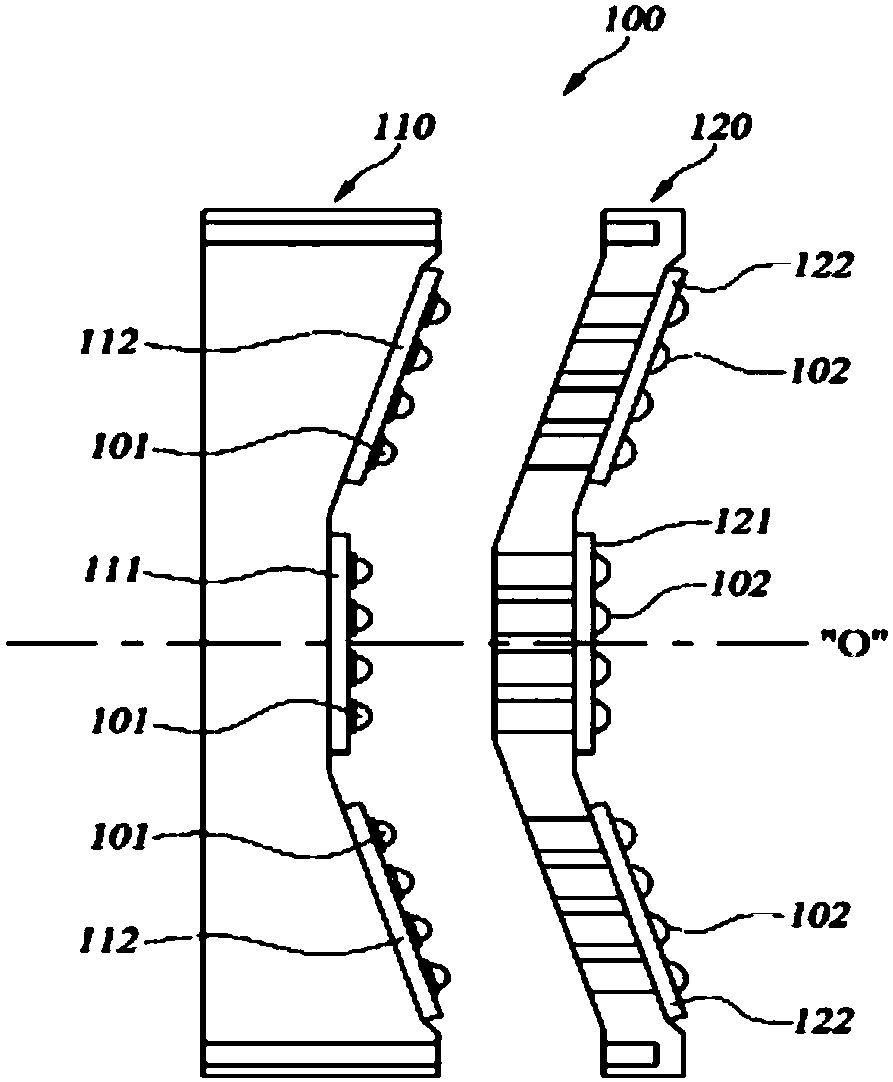
[0040] refer to figure 1 and figure 2 According to the present invention, the light source module unit 100 for exposure includes a light source panel 110 and an optical panel 120, and the light source panel 110 and the optical panel 120 are combined to form a unit unit by being arranged side by side.

[0041] The light source panel 110 is used as a supporting structure for supporting the circuit boards 111 and 112 while being mounted on the light source portion of an exposure device not shown, and can be formed into a flat plate by mold molding of a synthetic resin material o...


PUM


Abstract

The present invention provides an integrated light source module unit for exposure and an exposure device having the light source module unit, which can ensure exposure performance capable of dramatically improving the microfabrication and the resolution of exposure patterns and, at the same time, has been improved so as to be economically substitutable for the light source of a conventional exposure device since low power consumption and, particularly, ultraviolet (UV) lights having a high-efficiency and high-output single wavelength and short wavelength are ensured by maximizing light outputpower by a combination of modules each comprising: a center light source part comprising a light source panel formed by mounting a plurality of unit UV light emitting diodes (LEDs) on a circuit boardin a matrix array structure, and an optical panel formed by providing a plurality of unit condensing lenses on the optical panels, which are arranged at light-emitting sides of the LEDs to face the light source panel, in a matrix array structure in a state in which the condensing lenses are eccentric toward a random reference center axial line, which passes the center of a UV LED array on the light source panel, with respect to a major optical axis at the positions respectively corresponding to the LEDs; and a plurality of peripheral light source parts radially and equally arranged in an inclined state so as to face a major light-emitting axis of the unit UV LED of the center light source part.

Description

technical field [0001] The present invention relates to a light source for exposure, which is used in photolithography (Photolithography) process in order to form fine circuit patterns on semiconductor wafers or display panels, etc., and more specifically relates to an intensive light source module unit for exposure and equipped with The exposure device of the light source module unit, the light source module unit for intensive exposure is improved in the following form: the central light source part and the periphery are formed by a plurality of ultraviolet light emitting element (UV LED) arrays (arrays) and condenser lens arrays The form-integrated light source unit can effectively perform large-area exposure performance and economically replace the light source of the existing exposure device. Background technique [0002] For example, semiconductor elements or circuit boards (PCBs) built in as the main components of electrical and electronic equipment, and LCDs (Liquid C...

Claims


Application Information

Patent Timeline
IPC IPC(8): G03F7/20H01L21/027
Inventor 赵南稙印致亿朴钟沅宋友莉丁海一
Owner 赵南稙
Why Eureka
Try Eureka