Battery Holder and Dispensing Package

a battery and frame technology, applied in the field of battery holder, can solve the problems of troublesome and time-consuming, and achieve the effect of resisting dirt and debris infiltration and easy handling of the fram

Inactive Publication Date: 2016-11-10
TOOLS AVIATION
View PDF0 Cites 19 Cited by
  • Summary
  • Abstract
  • Description
  • Claims
  • Application Information

AI Technical Summary

Benefits of technology

[0021]Preferably, each compartment of the frame of the present invention has an open top end and is open at least through an edge portion of a bottom thereof, to permit contact of a user's thumb or finger onto a bottom surface of the battery held within the compartment. Each compartment is also open along a lower portion of the sidewall of the compartment contiguous with the open edge portion. Preferably, the open top end and the open portion of the bottom edge and sidewall can be covered by top and bottom membranes, such as film or foil seals, respectively. These openings allow the finger or thumb of the user to push through the bottom seal, or to push in the bottom seal, to the extent that allows the user to press the bottom of the battery and induce ejection of a battery from the compartment, by moving the battery through the top open end of the compartment. The top seal holds the battery within the compartment for retailing and storage purposes but will allow sufficient force from the user's finger to eject the battery through the top seal, breaking the seal. The bottom seal could be breakable or be a flexible or stretchable covering that need not be broken in order for the user to push up on the battery with a finger.
[0022]The top and bottom membranes close the openings of the frame and hold batteries therein. This can make the frame a package to hold batteries that is waterproof, or water resistant, and which resists infiltration of dirt and debris into the package. This aspect of the invention provides an attractive vehicle for marketing batteries and for retail sales of a battery and caddy combination.
[0023]The devices of the present invention provide further advantages over the known storage containers for batteries. The convenient and compact configurations of the frames of the devices allow the devices to be used in homes, planes, cars, offices and shops. The frames described herein keep batteries separated compared to loose batteries, to avoid inadvertent electrical contact between batteries. The compact arrangement and ergonomic shaping of the frames allows for easy handling of the frames and one-handed holding and dispensing of a selected battery. The open design of the sidewalls and a bottom wall of the frames allow the frames to shed debris which would otherwise collect in the compartments.

Problems solved by technology

During an emergency, if cabin lighting is lost or the pilot is preoccupied with controlling the aircraft, finding batteries loosely stored in a flight bag can be troublesome and time-consuming.

Method used


Image

  • Battery Holder and Dispensing Package
  • Battery Holder and Dispensing Package
  • Battery Holder and Dispensing Package

Examples


embodiment 200

[0083]FIGS. 15 and 16 illustrate a further embodiment device 300, similar to the embodiment 200 described in FIGS. 13 and 14 but with a modified container 306. Rather than a film hinge, a rounded pin 308 is formed onto a sidewall 314 of the container 306. A lid 320 is hingedly engaged to the pin 306, by C-shaped portions 322, in snap fit fashion. The lid 320 need not completely cover an open top 326 of the container 306 as shown. Such a configuration would allow a user to view into the container 306, through the areas on opposite sides of the lid 320, at least to a limited extent. The remaining portions of this container 306 are similar to the container 206.

[0084]FIG. 17 illustrates an accessory container 350 that can be used in any of the heretofore described embodiments. The container 350 includes a cylindrical body 354 having an open top 356 and a closed bottom 360. A lid 362 is connected to the body 354 by a film hinge 366. As can be readily understood, the lid 362 can be folded...

embodiment 700

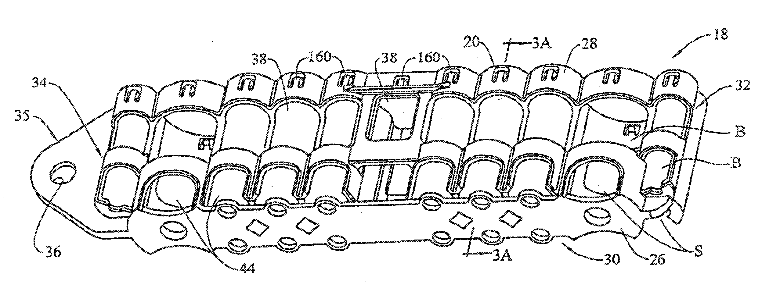
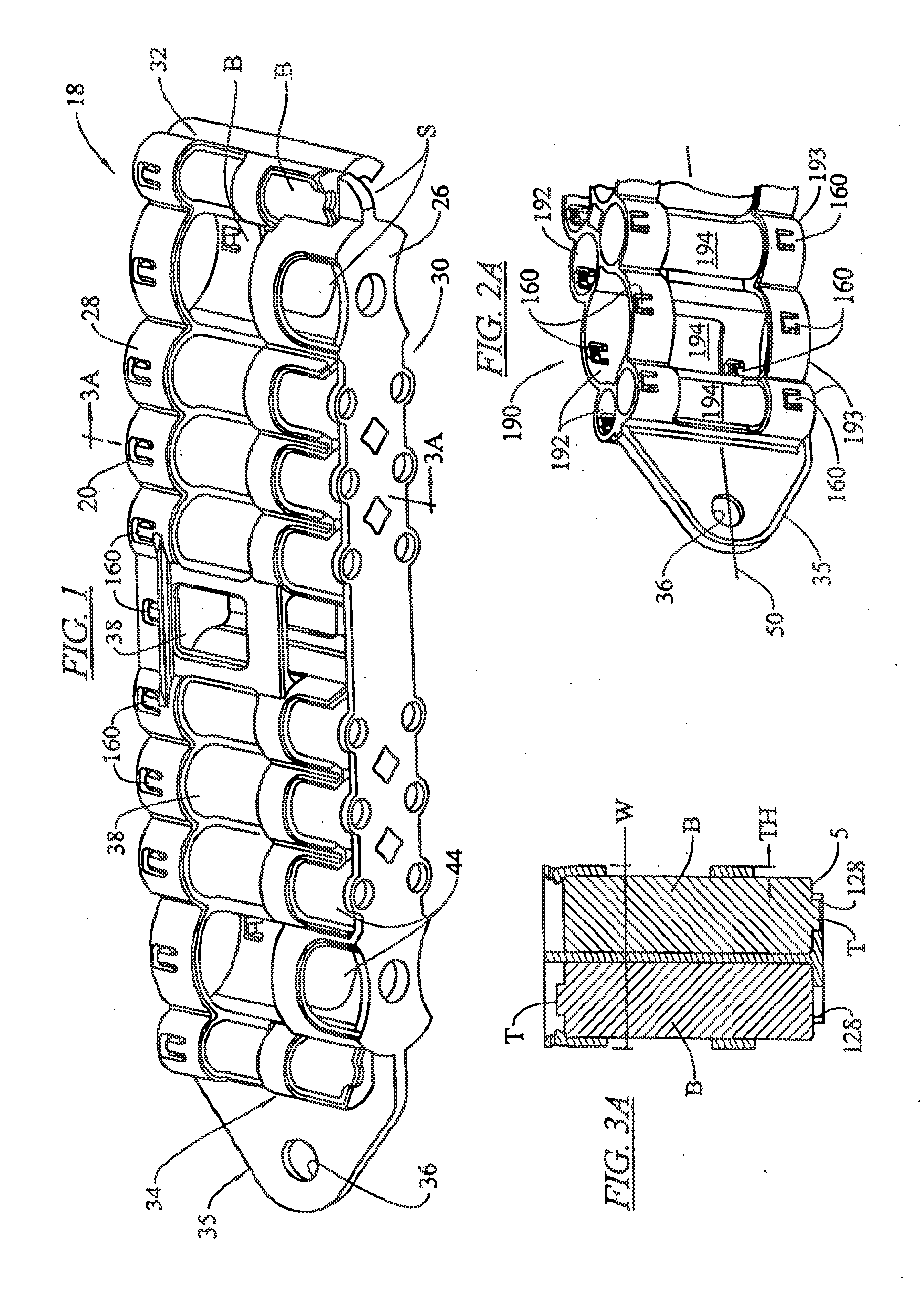
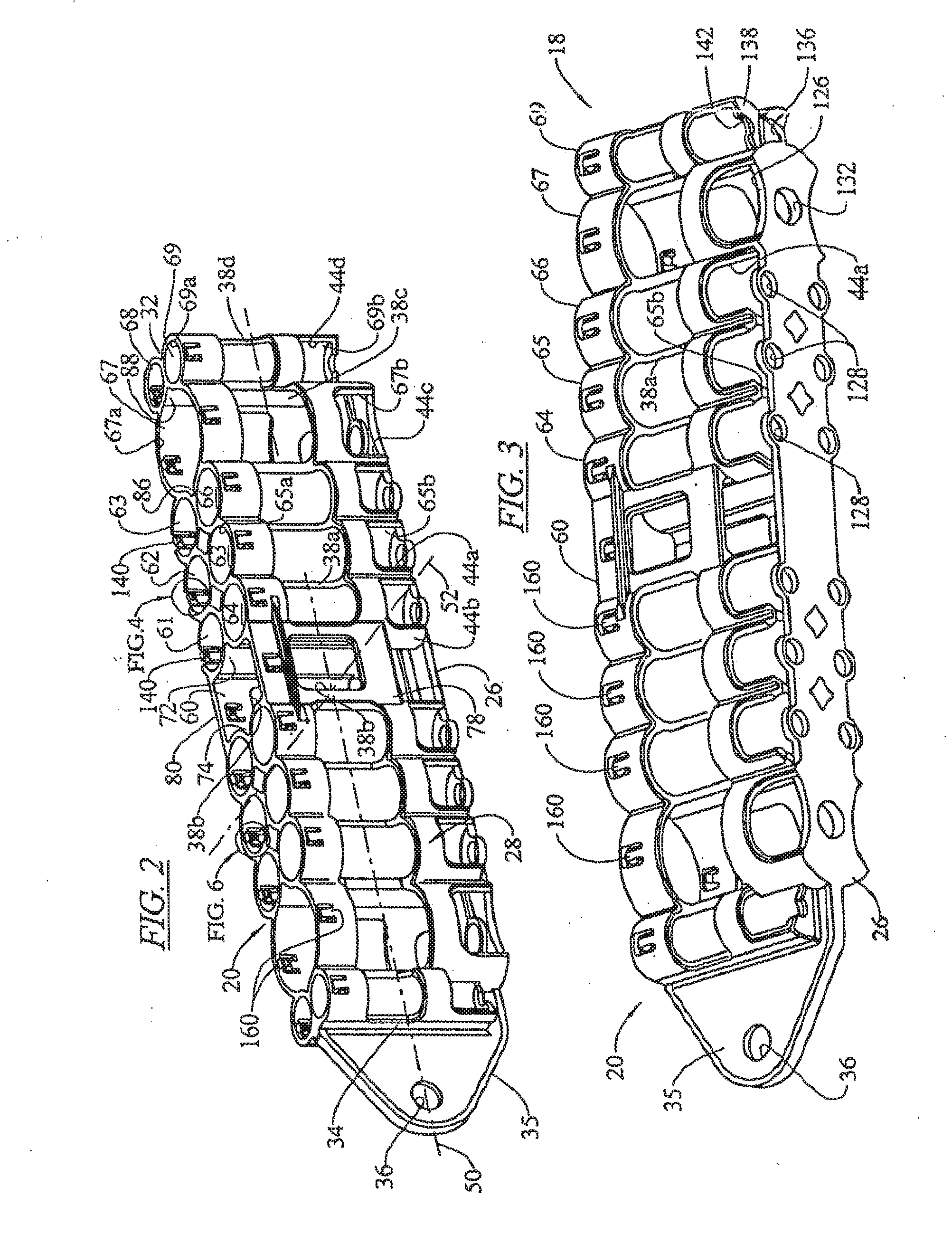
[0092]FIG. 22 illustrates an alternate embodiment 700 that can be configured in accordance with any of the heretofore described embodiments except as modified as described. For example the frame 700 can be configured substantially identically to the frame 20 shown in FIG. 1. The frame 700 includes contacts 706, 708 imbedded into, or otherwise carried by, the bottom wall 26 of the frame. The contacts 706, 708 are configured to engage the corresponding contacts 712, 714 of an inverted, rectangular 9 volt battery 716. A plurality of lamps 720a, 720b, 720c, 720d are arranged each within one void 722a, 722b, 722c, 722d that are arranged within the frame 20, 700.

[0093]As illustrated in FIGS. 12 and 22, the void 722c is formed centrally between the four bays 61, 62, 64, 65 and the void 722d is formed centrally between the four bays 62, 63, 64, 65. The voids 722a, 722b are similarly formed on an opposite longitudinal side of the frame 20, 700.

[0094]The lamps 720a, 720b, 720c, 720d are prefe...


PUM

PropertyMeasurementUnit
widthaaaaaaaaaa
widthaaaaaaaaaa
heightaaaaaaaaaa

Abstract

A battery holding and dispensing device can hold a plurality of batteries, in an assortment of battery sizes. The battery holding and dispensing device includes a frame having a plurality of compartments sized and shaped to each receive a battery of a particular battery size and each having a detent for releasably retaining the battery in the compartment. Each compartment has at least one opening in the bottom and lower side to expose a corner of the battery to allow finger ejection of the battery from the compartment past the detent, and to allow the user to touch the batteries to ascertain battery size by feel. The assortment of batteries held in the frame is preferably pre-selected to correspond to the batteries needed by a particular profession. An arrangement for illuminating the frame is provided.

Description

[0001]This application is a continuation of Ser. No. 13 / 461,563, filed May 1, 2012 which is a continuation of U.S. Ser. No. 11 / 974,513, filed Oct. 12, 2007, which is a continuation-in-part of PCT / US2006 / 016129, filed Apr. 27, 2006 which claims the benefit of U.S. Ser. No. 60 / 755,234, filed Dec. 12, 2005, and is a continuation-in-part of U.S. Ser. No. 11 / 218,874, filed Sep. 2, 2005.TECHNICAL FIELD OF THE INVENTION[0002]The present invention relates to a battery holder for use in storing, dispensing and packaging batteries.BACKGROUND OF THE INVENTION[0003]In the field of aviation, an airplane pilot is required to use many battery-powered devices, which devices serve either a primary or backup function. It is imperative that a pilot have ready access to a fresh supply of batteries in the event that batteries become inoperative or spent during flight. Some of these battery-powered devices include: handheld global positioning systems (GPS), handheld emergency radio transceivers, handheld...

Claims


Application Information

Patent Timeline
Patent Type & Authority Applications(United States)
IPC IPC(8): H01M2/10B65D83/04B65D85/00H01M50/213H01M50/227H01M50/267H01M50/271H01M50/293
CPCH01M2/1022B65D85/70H01M2/1005H01M2/1027B65D83/0445B65D83/02B65D2585/88Y02E60/10H01M50/267H01M50/293H01M50/213H01M50/227H01M50/271H01M50/256
Inventor FOREMAN, RICHARDFOREMAN, KATHLEENMOREAU, TIMOTHYCHERKAS, BRAD
Owner TOOLS AVIATION
Why Eureka
Try Eureka