
Portable electronic device

a portable electronic device and heat dissipation fan technology, applied in the field of electronic devices, can solve the problems of affecting the operation efficiency, difficult to dissipate the large amount of heat using the above-described heat dissipation method, and large amount of heat in the portable electronic device, so as to increase the air flow of the heat dissipation fan, effectively increasing the heat dissipation efficiency

Active Publication Date: 2016-11-10
ACER INC
View PDF0 Cites 4 Cited by
  • Summary
  • Abstract
  • Description
  • Claims
  • Application Information

AI Technical Summary

Benefits of technology

This patent is about a portable electronic device that can increase its heat dissipation efficiency by raising the heat dissipation fan to the outer surface of the device through an opening in the housing. This action increases air flow and improves heat convection, making the device cooler and more efficient when in high demand for heat dissipation.

Problems solved by technology

During operation, such electronic devices usually generate heat, which can affect the operation efficiency.
However, when operating in high performance mode, the faster the performance, the more heat is generated, causing a large amount of heat in portable electronic devices.
Aggravated by miniaturization of portable devices, it is difficult to dissipate the large amount of heat using the above-described heat dissipation method.

Method used


Image

  • Portable electronic device
  • Portable electronic device
  • Portable electronic device

Examples


Embodiment Construction

[0015]The description of the invention and other technical contents, features, and benefits are more clearly presented in the embodiments with the figures below. Words of direction referred to in the embodiments below, such as “up,”“down,”“forward,”“backward,”“left,”“right,” etc. refer to directions in the figures only. As such, the words of direction are used to illustrate instead of limiting the invention. Also, in the embodiments below, identical or similar reference numerals are adopted for identical or similar elements.

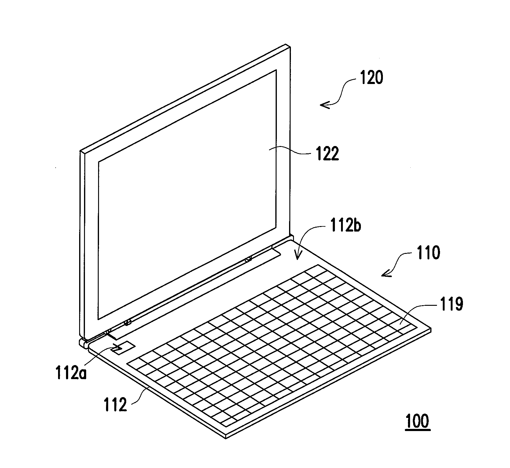
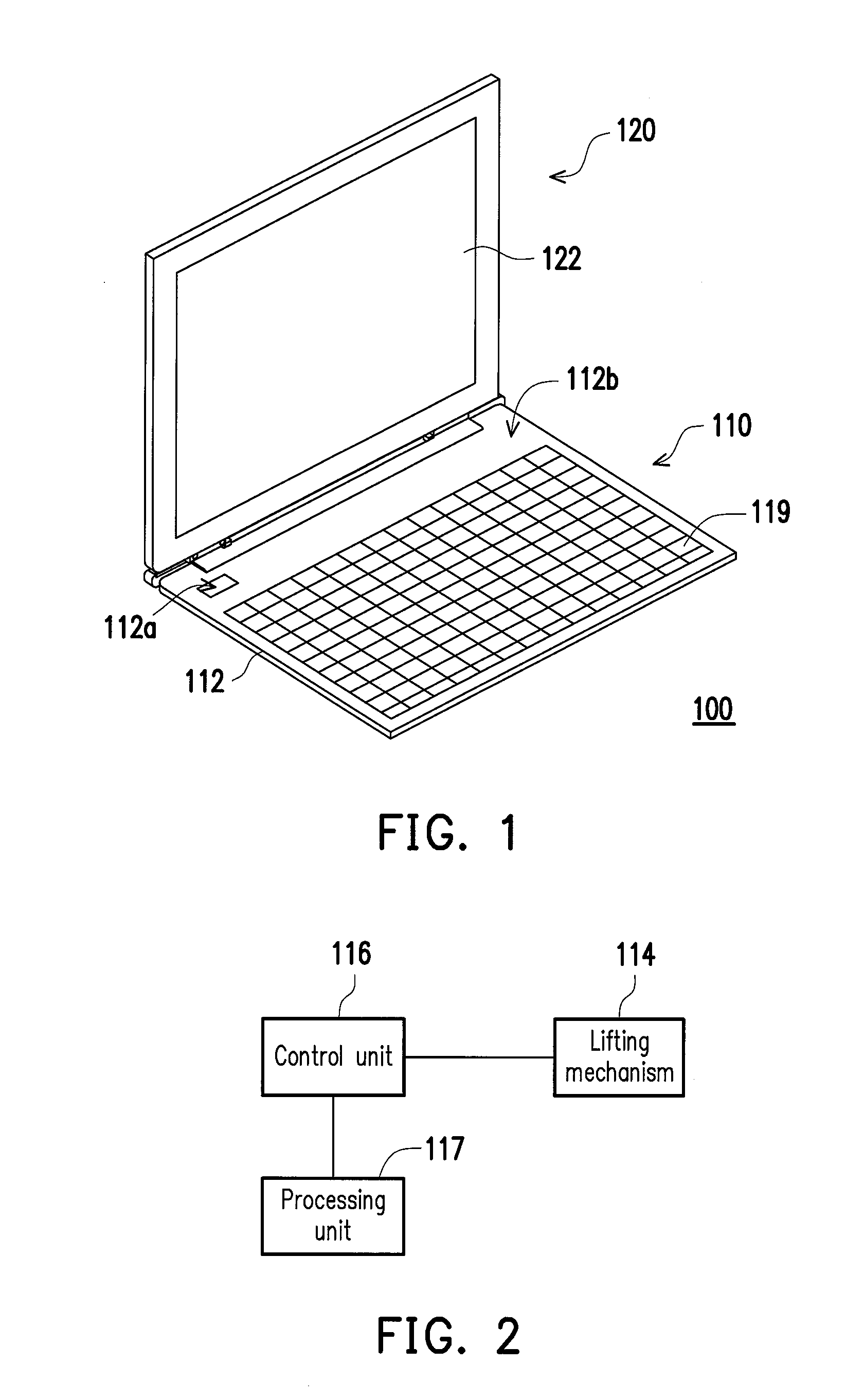
[0016]FIG. 1 is a schematic of a portable electronic device of an embodiment of the invention. Referring to FIG. 1, in the present embodiment, the portable electronic device 100 may be a notebook computer which may, as shown in FIG. 1, include a first body 110 and a second body 120, wherein the second body 120 is pivotally connected to the first body 110 to rotate with respect to the first body 110. Specifically, the first body 110 may include a housing 112 and a...


PUM


Abstract

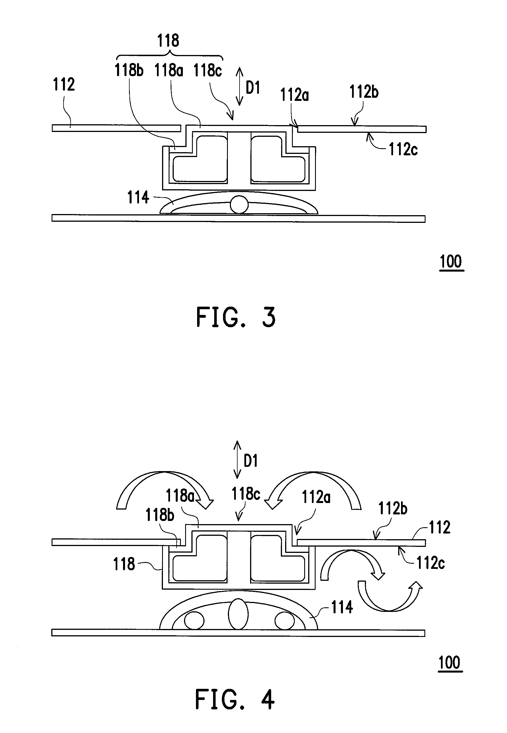
The electronic portable device of the invention includes a housing, a lifting mechanism, a controlling unit, and a heat dissipation fan. The housing includes an opening The lifting mechanism is movably disposed in the housing and corresponds to the opening. The lifting mechanism is configured to move toward or away from the opening. The control unit is coupled to the lifting mechanism and configured to control the lifting mechanism to move toward or away from the opening. The heat dissipation fan is disposed on the lifting mechanism and corresponds to the opening. When the lifting mechanism moves towards the opening, the heat dissipation fan is lifted toward the opening by the lifting mechanism, and is protruded from an outer surface of the housing through the opening.

Description

CROSS-REFERENCE TO RELATED APPLICATION[0001]This application claims the priority benefit of Taiwan application serial no. 104114718, filed on May 8, 2015. The entirety of the above-mentioned patent application is hereby incorporated by reference herein and made a part of this specification.BACKGROUND OF THE INVENTION[0002]1. Field of the Invention[0003]The invention relates to an electronic device, and more particularly, to a portable electronic device.[0004]2. Description of Related Art[0005]With the development of technologies in recent years, electronic devices such as notebook, tablet PC, and smart phone have frequently appear in daily life. During operation, such electronic devices usually generate heat, which can affect the operation efficiency. As a result, the interiors of electronic devices are frequently configured with heat dissipation modules or elements in order to assist the dissipation of heat out of the electronic devices.[0006]Heat dissipation fan is a common elemen...

Claims


Application Information

Patent Timeline
IPC IPC(8): H05K7/20G06F1/20
CPCH05K7/20145H05K7/20209G06F1/203G06F1/206
Inventor HUANG, YI-TATAI, WEN-CHIEHLING, CHENG-NAN
Owner ACER INC
Learn More