Thermoelectric generator using in-situ passive cooling

a technology of passive cooling and thermoelectric generator, which is applied in the direction of electrochemical generators, secondary cells servicing/maintenance, electrical apparatus, etc., can solve the problems of insufficient cooling, thermoelectric module failure, and inability to maintain a stable cold side surface temperature, etc., to achieve greater heat dissipation, large liquid volume, and large heat capacity

Active Publication Date: 2021-03-30
CAMPEAU GERARD R
View PDF8 Cites 2 Cited by
  • Summary
  • Abstract
  • Description
  • Claims
  • Application Information

AI Technical Summary

Benefits of technology

[0012]In another aspect, a plurality of heat exchanger vessels of similar configuration are provided. In this case, the combined retained liquid volume is at least 10 liters of the liquid coolant. The combined liquid volume provides larger heat capacity and greater heat dissipation. In addition, at least a second heat absorber is provided to conduct heat from a common heat source such as the exhaust flue stream of a wood fired heating stove, a natural gas fireplace appliance, or other biomass combustion site. This embodiment can be further scaled with more vessels, larger liquid volumes, and more heat absorbers.
[0013]In another aspect, an external Direct Current (D.C.) fan powered by the present thermoelectric generator system provides convective air flow directed to the exterior fins of a heat exchanger vessel. This configuration improves the flow of heat from the external fins particularly in conditions of elevated ambient temperature and humidity.

Problems solved by technology

However, this format does not maintain a stable cold side surface temperature.
Without sufficient liquid there is insufficient cooling and the thermoelectric module fails due to excessive heat concentration on the hot side of the module.
In this configuration, the temperature of the hot side is easily pushed beyond the recommended temperature and will be damaged.
This configuration produces poor temperature differential because the side walls of the vessel containing the coolant are fully within the heat envelope of the combustion source and this raises the coolant temperature.
Moreover, if the internal battery is discharged below the threshold to operate the fan, the system's heating and cooling fails, the power from the thermoelectric module fails, and the thermoelectric module can be exposed to excessive temperature.

Method used


Image

  • Thermoelectric generator using in-situ passive cooling
  • Thermoelectric generator using in-situ passive cooling
  • Thermoelectric generator using in-situ passive cooling

Examples


embodiment 80

[0049]FIG. 8 is an exploded view of an embodiment 80, using thermoelectric generator systems arranged to produce voltage from the heated exhaust of a wood burning stove 20 or other hearth device. This arrangement absorbs heat from the exhaust using heat absorbers 42 and conducts the heat to the hot side of modules 7. The cold side of modules 7 is maintained by the heat exchanger vessels 1. Uniquely, the two heat exchanger vessels 1 are mounted in the cold air return pipes 23 of the stove 20. Cold air return pipes 23 with an inside diameter of at least 102 mm are designed to fit over each heat exchanger vessel 1 to allow cool air to flow past external fins 9 of each heat exchanger vessel 1. This convective cooling improves the removal of heat from the cold side of modules 7. A servo mechanism consisting of damper 22, a stepper motor 21, and temperature feedback measurement sensor 82 is operably configured to control the position of the damper 22 in response to the measured temperatur...

embodiment 60

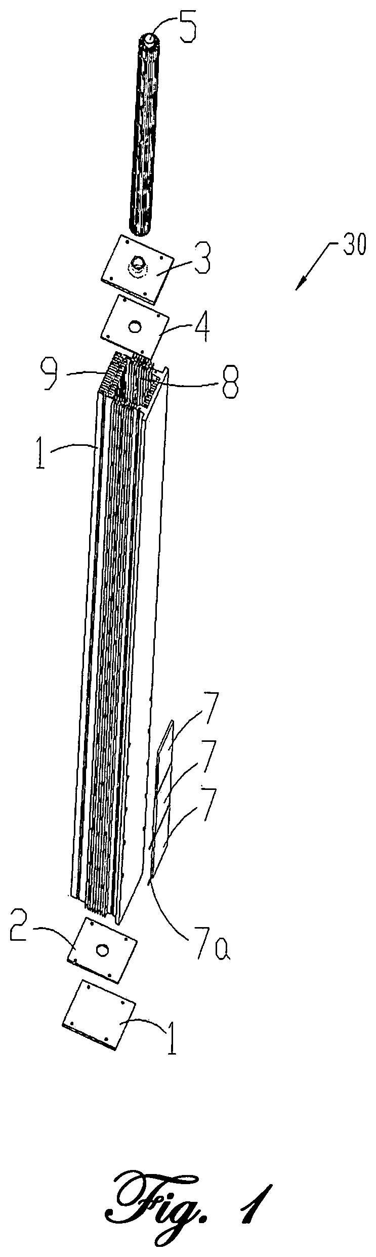
[0051]FIG. 9 is an isometric view of an embodiment 60 using two heat exchanger vessel assemblies 30 of FIG. 1, two heat absorber plates 62, and heat sourced from a combustion site of a hearth device such as a natural gas fireplace appliance 65. Two heat absorber plates 62 are attached to the steel rear side of the fireplace 65 conduct heat to the hot side of thermoelectric modules (not visible in this view) and two heat exchanger vessels 1 are positioned to dissipate heat from the cold side of each module. In addition, as part of a typical gas fireplace installation, there are two 12 Volt D.C. blower fan motors 66 that are primarily intended to direct the heat from the inside of the fireplace through a vent near the top of the enclosure to warm the external air in the area where the fireplace is installed. In this embodiment, the fan motors are oriented to also allow cool air to flow past external fins 9 (indicated by the bold arrows), of the heat exchanger vessel 1. When the voltag...


PUM

PropertyMeasurementUnit
volumeaaaaaaaaaa
heightaaaaaaaaaa
internal diameteraaaaaaaaaa

Abstract

A portable electrical power generation system using thermoelectric modules to produce voltage from a temperature differential. The temperature differential is maintained using a passive cooling system including a retained liquid coolant and heat from a heated fluid.

Description

FEDERALLY SPONSORED RESEARCH[0001]Not applicableSEQUENCE LISTING OR PROGRAM[0002]Not applicableFIELD OF THE INVENTION[0003]The present invention relates to portable and permanent generators of electrical energy and more specifically to generators using solid state Seebeck Effect thermoelectric (TEG) modules and various thermodynamic arrangements including passive cooling methods to maintain suitable module operation.BACKGROUND OF THE INVENTION[0004]Modern Seebeck Effect thermoelectric modules transform a temperature difference across the module, between the hot and cold sides of the device, into a usable voltage. While the temperature difference is maintained, the module can provide a continuous power source. A module in these conditions is considered an on-demand electrical energy generation system.[0005]Passive Liquid Cooling:[0006]The prior art describes thermoelectric generation systems using passive liquid cooling. For example U.S. Pat. No. 8,674,530 B2 describes a cooking pot ...

Claims


Application Information

Patent Timeline
Patent Type & Authority Patents(United States)
IPC IPC(8): H01L35/32H01M10/44
CPCH01L35/32H01M10/443Y02E60/10H10N10/17
Inventor CAMPEAU, GERARD R
Owner CAMPEAU GERARD R
Why Eureka
Try Eureka